Locked-rotor processing method and device for position-sensorless DC brushless motor

A technology of brushless DC motor and processing method, which is applied to control electromechanical transmission, control generator, motor generator control, etc., can solve the problems of large acquisition error, large rotor speed error, and inability to provide large torque.

Pending Publication Date: 2020-11-10
BEIJING JINGWEI HIRAIN TECH CO INC
View PDF0 Cites 0 Cited by
  • Summary
  • Abstract
  • Description
  • Claims
  • Application Information

AI Technical Summary

Problems solved by technology

However, since the back electromotive force is proportional to the rotor speed of the motor, the back electromotive force is relatively small when the rotor speed is reduced to a low value due to a stall of the brushless DC motor; and when the back electromotive force is small, the acquisition error of the back electromotive force Larger, resulting in a larger error in the estimation of the rotor speed, and a larger error in the obtained rotor position
[0004] When the rotor position cannot be obtained, the field-oriented control algorithm cannot apply a magnetic field in the correct direction according to the current rotor position, and thus cannot generate a large driving torque. The position sensor brushless DC motor also provides a large torque, resulting in a weak resistance to external force interference of the position sensorless DC brushless motor
In the pump motor system, since there may be impurities and foreign objects in the water or oil circuit of the pump, when these foreign objects block the rotor and cause the brushless DC motor to stall, the pump body will often fail to operate normally and the pump body will be lost. Function

Method used


Image

  • Locked-rotor processing method and device for position-sensorless DC brushless motor
  • Locked-rotor processing method and device for position-sensorless DC brushless motor
  • Locked-rotor processing method and device for position-sensorless DC brushless motor

Examples


Embodiment Construction

[0050]The following will clearly and completely describe the technical solutions in the embodiments of the present invention with reference to the accompanying drawings in the embodiments of the present invention. Obviously, the described embodiments are only some, not all, embodiments of the present invention. Based on the embodiments of the present invention, all other embodiments obtained by persons of ordinary skill in the art without making creative efforts belong to the protection scope of the present invention.

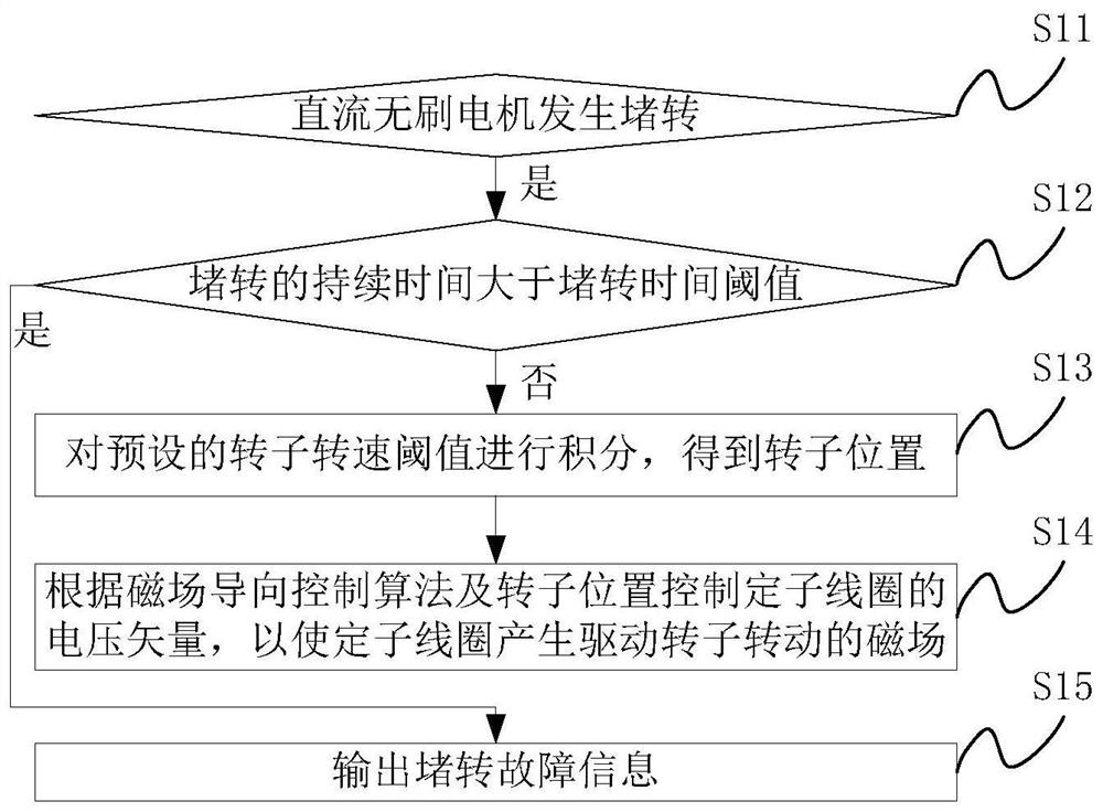
[0051] see figure 1 , a position sensorless DC brushless motor stall processing method provided in an embodiment of the present invention, the method may include the following steps:

[0052] S11: Determine whether the brushless DC motor is stalled, and if so, execute step S12.

[0053] When the DC brushless motor does not stall, the rotor position can be calculated according to the existing rotor position estimation algorithm. Specifically, a motor back-emf ...


PUM


Abstract

The invention provides a locked-rotor processing method and device for a brushless DC motor without a position sensor, and the method comprises the steps: carrying out the integration of a preset rotor rotating speed threshold value in a period of time when the brushless DC motor just carries out the locked-rotor, and obtaining the position of a rotor; and controlling the voltage vector of the stator coil according to the rotor position through a magnetic field steering control algorithm. Since the rotor speed threshold is a constant, the rotor position obtained by integration of the thresholdis a constant-speed rotation angle, and the stator coil generates a constant-speed rotation magnetic field. Although the rotor stops rotating and is unknown in position during locked-rotor, a sectionof angle always can provide driving torque for the rotor under the action of the magnetic field rotating at the constant speed, the rotor is subjected to periodic impact of the driving torque when locked-rotor happens to the DC brushless motor, and the rotor restarts to rotate when locked-rotor resistance torque is smaller than the driving torque, so the external force interference resistance ofthe brushless DC motor without the position sensor is enhanced.

Description

technical field [0001] The invention relates to the technical field of electric pumps, and more specifically, to a method and device for dealing with a stall of a position sensorless DC brushless motor. Background technique [0002] In existing new energy vehicles, because there is no engine, power cannot be taken from the engine crankshaft, and the water pump and oil pump in the vehicle are gradually changed from mechanical pumps to electric pumps. Due to cost considerations, the power source of the pump body of these electric pumps usually adopts a brushless DC motor without a position sensor. In the current position sensorless brushless DC motor control scheme, since there is no physical position sensor, it is necessary to estimate the rotor position of the motor through an algorithm. [0003] At present, the most widely used method for estimating the rotor position of a brushless DC motor is to estimate the rotor speed of a brushless DC motor through an established moto...

Claims


Application Information

Patent Timeline
IPC IPC(8): H02P21/18H02P21/28H02P21/13
CPCH02P21/18H02P21/28H02P21/13
Inventor 常嘉航
Owner BEIJING JINGWEI HIRAIN TECH CO INC
Why Eureka
Try Eureka