
Rotor turning machine

A turning and rotor technology, applied in the field of rotors, can solve the problems of low production efficiency and low turning precision

Pending Publication Date: 2020-11-13
广东集捷智能装备有限公司
View PDF0 Cites 1 Cited by
  • Summary
  • Abstract
  • Description
  • Claims
  • Application Information

AI Technical Summary

Problems solved by technology

In the prior art, the rotor is manually turned, which has low production efficiency and low turning precision, so it is necessary to improve it

Method used


Image

  • Rotor turning machine
  • Rotor turning machine
  • Rotor turning machine

Examples


Embodiment Construction

[0020] The following are only preferred embodiments of the present invention, and therefore do not limit the protection scope of the present invention.

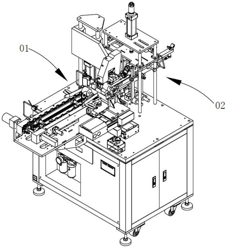
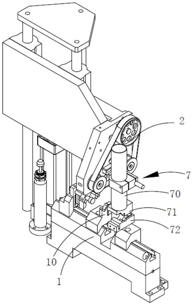
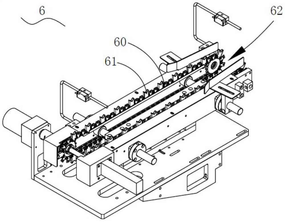
[0021] Such as Figures 1 to 6 As shown, a rotor turning machine provided by the present invention includes a turning station 01 and a copper sand cleaning station 02. The turning station 01 is provided with a turning seat 1 for carrying the rotor, and a first Pressing arm pulley mechanism 2 and turning tool module 3 for turning the rotor surface, copper sand cleaning station 02 is provided with copper sand cleaning mechanism 4, and between turning station 01 and copper sand cleaning station 02 is provided with reciprocating material transfer Mechanism 5 is used to transfer the rotor in the turning station 01 to the copper sand cleaning station 02. The first pressing arm pulley mechanism 2 is provided with a pressing arm, a pulley mechanism installed on the front end of the pressing arm and a mechanism for driving the pressin...


PUM


Abstract

The invention discloses a rotor turning machine. The rotor turning machine comprises a turning station and a copper sand sweeping station; the turning station is provided with a turning base used forbearing a rotor, a first pressing arm belt wheel mechanism arranged above the turning base and a turning tool module used for turning the surface of the rotor; the first pressing arm belt wheel mechanism is used for driving the rotor in the turning base to rotate; the copper sand sweeping station is provided with a copper sand sweeping mechanism; and a reciprocating material moving mechanism is arranged between the turning station and the copper sand sweeping station and used for moving the rotor in the turning station into the copper sand sweeping station. According to the rotor turning machine, manual operation in the prior art is replaced, the production efficiency is greatly improved, the turning precision is improved, and automatic production of equipment is achieved.

Description

technical field [0001] The invention relates to the technical field of rotors, in particular to a rotor turning machine. Background technique [0002] In the assembly process of the motor rotor, the die-cast rotor blank needs to be turned to process the outer peripheral wall of the rotor. In the prior art, the rotor is manually turned, which has low production efficiency and low turning precision, so it is necessary to improve it. Contents of the invention [0003] In view of the deficiencies in the prior art, the purpose of the present invention is to provide a rotor turning machine, which replaces the manual operation in the prior art, greatly improves the production efficiency, improves the turning precision, and realizes the automatic production of the equipment. [0004] In order to achieve the above object, the technical solution adopted in the present invention is: a rotor turning machine, which includes a turning station and a copper sand cleaning station, the tur...

Claims


Application Information

Patent Timeline
IPC IPC(8): B23B5/00B23B15/00B23Q11/00H02K15/02
CPCB23B5/00B23Q7/00B23Q11/0042B23Q11/0046H02K15/02
Inventor 武昱
Owner 广东集捷智能装备有限公司
Learn More