
Unloading device for production of numerically controlled electromechanical equipment and method of use thereof

A technology of unloading device and electromechanical equipment, which is applied in the direction of metal processing, etc., can solve the problems affecting the processing of parts, the increase in the number of defective products, and the deviation of shaft parts, so as to achieve the effect of reducing the number of defective products

Active Publication Date: 2022-02-01
深圳市正源智能刀模设备有限公司
View PDF10 Cites 0 Cited by
  • Summary
  • Abstract
  • Description
  • Claims
  • Application Information

AI Technical Summary

Problems solved by technology

[0004] In view of the unloading work of CNC electromechanical equipment in the existing technology, the loading and unloading of parts is manually operated, resulting in a large amount of labor for the staff. In order to meet the needs of production, it is necessary to manually repeat the loading and unloading actions, causing great harm to the staff. At the same time, in the repeated labor process, the fatigue of the workers will easily lead to the misalignment of the shaft parts, which will affect the processing of the parts and lead to the increase in the number of defective products. The loading and unloading operation of parts can effectively reduce the labor load of the staff, which can not only meet the production requirements, but also prevent the staff from causing great damage to the staff due to manual repeated loading and unloading actions, and avoid the misalignment of shaft parts due to worker fatigue, which will affect zero. The problem of the processing quality of the parts occurs, which can effectively reduce the number of defective products, and then improve the production efficiency and product quality. The unloading device for the production of numerical control electromechanical equipment and its use method

Method used


Image

  • Unloading device for production of numerically controlled electromechanical equipment and method of use thereof
  • Unloading device for production of numerically controlled electromechanical equipment and method of use thereof
  • Unloading device for production of numerically controlled electromechanical equipment and method of use thereof

Examples


Embodiment Construction

[0039] In order to facilitate the understanding of those skilled in the art, the present invention will be further described below in conjunction with the embodiments and accompanying drawings, and the contents mentioned in the embodiments are not intended to limit the present invention.

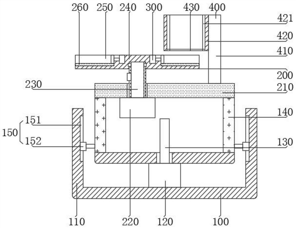
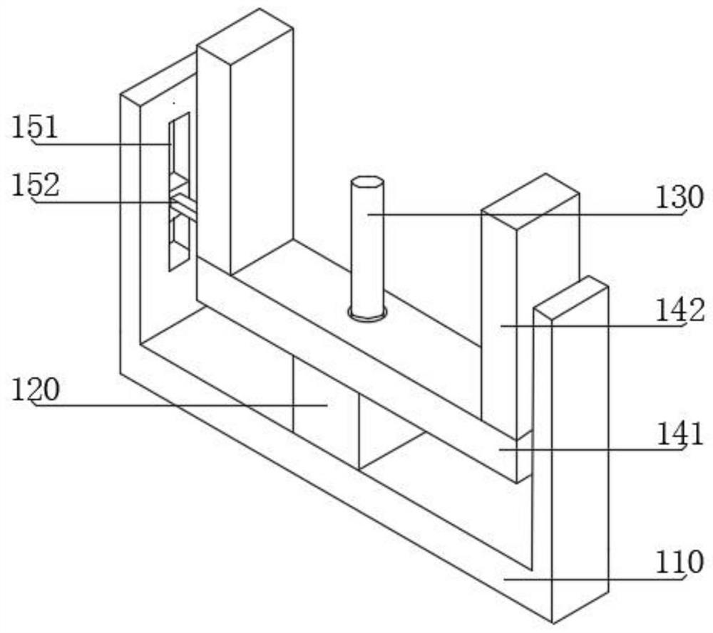
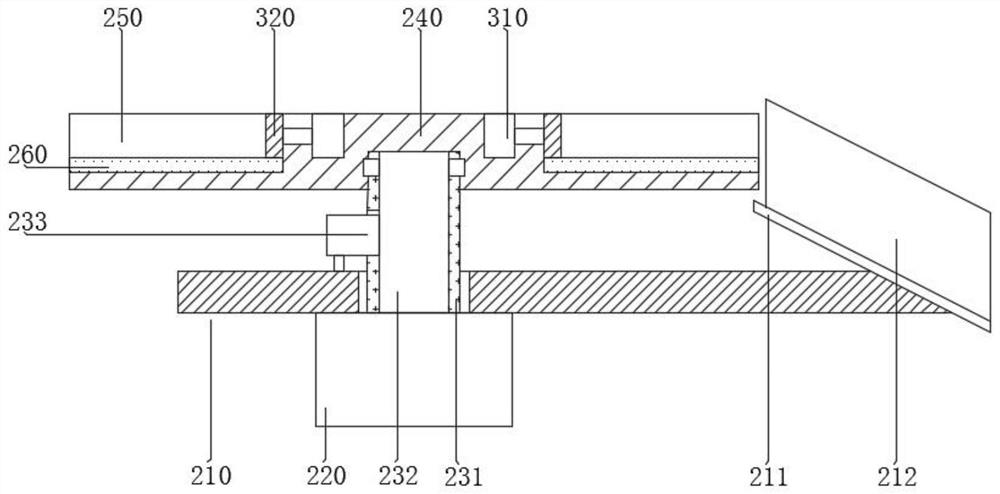
[0040] Such as figure 1 As shown, a discharge device for the production of numerical control electromechanical equipment includes a lifting assembly 100, a rotating assembly 200, a pushing assembly 300 and a feeding assembly 400, the rotating assembly 200 is installed on the side of the lifting assembly 100, and the pushing assembly 300 is installed On the side of the rotating assembly 200, the feeding assembly 400 is installed on the side of the lifting assembly 100, wherein the lifting assembly 100 is used for lifting and lowering to facilitate height adjustment; the rotating assembly 200 is used for transferring shaft parts, pushing materials The assembly 300 is used to push the shaft par...


PUM


Abstract

The invention discloses an unloading device for the production of numerically controlled electromechanical equipment, which includes a lifting assembly, a rotating assembly, a pushing assembly and a feeding assembly. The assembly includes a support plate, a rotating motor, a drive shaft and a turntable, the pushing assembly includes an electric push rod and a pushing plate, the feeding assembly includes a connecting frame and a storage box, the feeding assembly includes a connecting frame and a storage box, and the connecting frame is installed on the top of the support plate. The invention also discloses the use method of the unloading device. The invention can replace the manual loading and unloading operation of the parts, effectively reduce the labor workload of the staff, not only meet the production requirements, but also prevent the staff from causing serious damage to the staff due to repeated manual loading and unloading actions. Large damage can avoid the problem that shaft parts are easily misaligned due to worker fatigue and affect the processing quality of parts, and can effectively reduce the number of defective products, thereby improving production efficiency and product quality.

Description

technical field [0001] The invention belongs to the technical field of numerically controlled electromechanical equipment production, and specifically relates to a discharge device for the production of numerically controlled electromechanical equipment. Background technique [0002] CNC lathe is one of the most widely used CNC machine tools at present. It is mainly used for cutting the inner and outer cylindrical surfaces of shaft parts or disk parts, inner and outer conical surfaces with any cone angle, complex rotary inner and outer curved surfaces, and cylindrical and conical threads. It can also perform processing such as grooving, drilling, reaming, reaming and boring. [0003] At present, the fixing of the parts is generally by manually placing the shaft parts on the upper part of the chuck, and then using the chuck to fix the shaft parts. The loading and unloading of the parts are all manually operated, which causes the staff to The amount of labor is large. In orde...

Claims


Application Information

Patent Timeline
Patent Type & Authority Patents(China)
IPC IPC(8): B23B15/00
CPCB23Q7/00
Inventor 黄朝阳朱方固
Owner 深圳市正源智能刀模设备有限公司
Learn More