Automatic discharging mechanism for welding auto parts

A product and automobile technology, applied in the field of automatic stripping mechanism, can solve the problems of waiting for welding time, reduced welding processing efficiency of automobile product parts, no automatic stripping function, etc., to achieve the effect of easy welding and stable clamping

Active Publication Date: 2020-11-13
丰宁满族自治县宏亭汽车部件有限公司
View PDF7 Cites 0 Cited by
  • Summary
  • Abstract
  • Description
  • Claims
  • Application Information

AI Technical Summary

Problems solved by technology

[0004] The object of the present invention is to provide an automatic stripping mechanism for automobile welding products, aiming at solving the problem that after the welding process of automobile welding products in the prior art is completed by welding equipment, it is generally taken off manually, and the With automatic stripping function, because the temperature of the product after welding is too high, it is necessary to wait for the temperature of the product to drop before taking it off manually, so that the welding time of the next product needs to wait, so that the welding processing efficiency of the automotive product is improved Greatly reduces the problem
It is aimed at solving the problem that after the welding process of the automobile welding product parts in the prior art is completed by the welding device, it is generally taken off manually, without the automatic stripping function, because the temperature of the product parts after welding is too high, manual When picking up the parts, it is necessary to wait for the temperature of the product to drop before taking it off, which makes the welding time of the next product part need to wait, which greatly reduces the welding processing efficiency of the automotive product part

Method used


Image

  • Automatic discharging mechanism for welding auto parts
  • Automatic discharging mechanism for welding auto parts
  • Automatic discharging mechanism for welding auto parts

Examples


Embodiment 1

[0028] see Figure 1-5 , the present invention provides the following technical solutions:

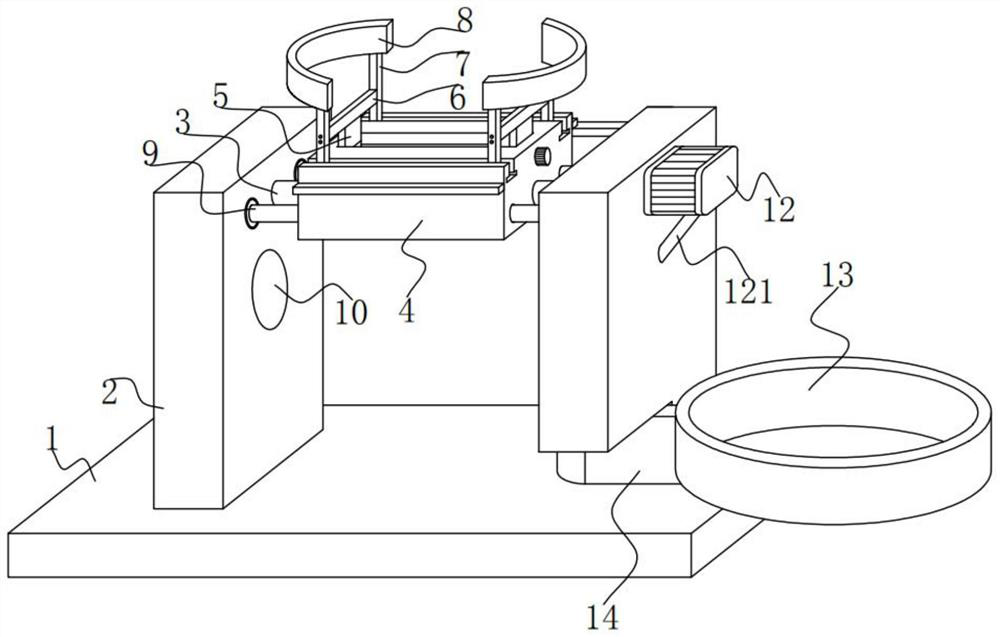
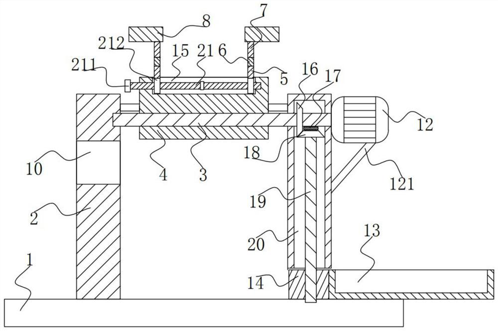
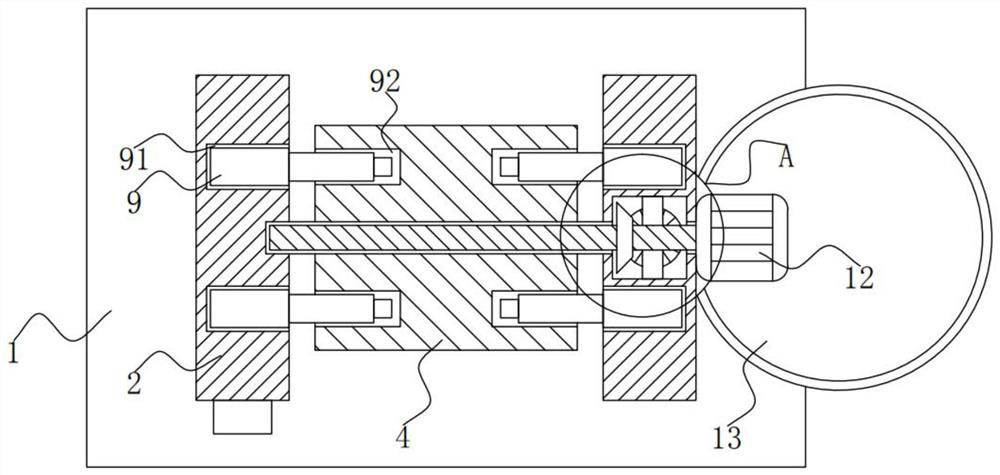
[0029]An automatic stripping mechanism for automobile welding products, including a base 1, two support plates 2 are fixed on the upper end of the base 1, and a rotating shaft 3 is rotatably connected between the adjacent ends of the two supporting plates 2, and the rotating shaft 3 The circumferential surface is fixed with a welding table 4, the right end of the rotating shaft 3 runs through the right end of the supporting plate 2 on the right side, and the right end of the supporting plate 2 on the right side is fixed with a servo motor 12, the output shaft of the servo motor 12 is fixed between the rotating shaft 3, The upper end of the welding table 4 is provided with a screw mandrel groove 15, and the left and right inner walls of the screw mandrel groove 15 are all rotatably connected with a screw mandrel 21, and the adjacent ends of the two screw mandrels 21 are fixed between th...


PUM


Abstract

The invention provides an automatic discharging mechanism for welding auto parts, and belongs to the technical field of auto welding equipment. The automatic discharging mechanism for welding the autoparts comprises a base. Two supporting plates are fixed to the upper end of the base. A rotating shaft is rotationally connected between the ends, close to each other, of the two supporting plates. Awelding table is fixed to the circumferential surface of the rotating shaft. The right end of the rotating shaft penetrates through the right end of the supporting plate on the right side. A servo motor is fixed to the right end of the supporting plate on the right side. An output shaft of the servo motor is fixed to the rotating shaft. A lead screw groove is formed in the upper end of the welding table. Lead screws are rotationally connected to the left inner wall and the right inner wall of the lead screw groove correspondingly. The ends, close to each other, of the two lead screws are fixed to each other. The left end of the lead screw on the left side penetrates through the left end of the welding table and extends outwards. After the auto parts are welded by the automatic dischargingmechanism, the auto parts are automatically discharged into a collecting groove, other auto parts can continue to be welded, the welded auto parts are more conveniently collected, and welding efficiency is greatly improved.

Description

technical field [0001] The invention belongs to the technical field of automobile welding equipment, and in particular relates to an automatic stripping mechanism for automobile welding product parts. Background technique [0002] With the increasingly fierce competition in the auto parts processing market, the popularization of the concept of environmental protection, and the continuous upgrading and application of technology, there are many types of auto parts. In the process of auto parts processing, welding is a frequently used method. [0003] After the existing automobile welding product parts are welded by welding equipment, they are generally taken off manually, without the automatic stripping function. Because the temperature of the product parts after welding is too high, it is necessary to wait for manual pick-up. The product can only be removed after the temperature of the product is lowered, so that the welding time of the next product part needs to wait, and th...

Claims


Application Information

Patent Timeline
Patent Type & Authority Applications(China)
IPC IPC(8): B23K37/04B23K37/00
CPCB23K37/0435B23K37/0461B23K37/00B23K2101/006
Inventor 吴应举
Owner 丰宁满族自治县宏亭汽车部件有限公司
Why Eureka
Try Eureka