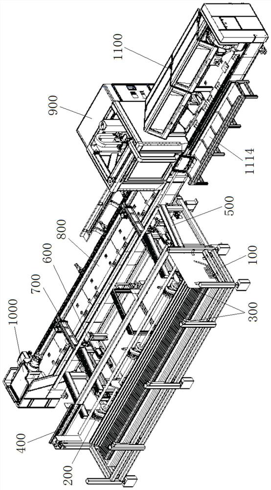
Automatic pipe cutting equipment

A cutting equipment and pipe material technology, applied in the field of automatic pipe material cutting equipment, can solve the problems of improvement, unfavorable production capacity, manual material distribution and low efficiency of feeding operations.

Pending Publication Date: 2020-11-13
佛山汇百盛激光科技有限公司
View PDF0 Cites 9 Cited by
  • Summary
  • Abstract
  • Description
  • Claims
  • Application Information

AI Technical Summary

Problems solved by technology

[0002] At present, the machinery industry uses cutting machines to cut pipes to mass-produce pipes of a specific length. In order to achieve the purpose of continuous cutting, it usually uses simple mechanical equipment to realize feeding one by one after manual auxiliary distribution. The feeding operation efficiency is low, and it is easy to have large operation errors, so that the placement position of the pipe material is not accurate, which leads to the accurate clamping of the chuck of the cutting machine. It increases the labor cost, which is not conducive to the improvement of production capacity, and it is easy to cause damage to the health of workers during the work process.

Method used


Image

  • Automatic pipe cutting equipment
  • Automatic pipe cutting equipment
  • Automatic pipe cutting equipment

Examples


Embodiment Construction

[0056] The specific implementation manners of the present invention will be further described in detail below in conjunction with the accompanying drawings and embodiments. The following examples are used to illustrate the present invention, but are not intended to limit the scope of the present invention.

[0057]In describing the present invention, it is to be understood that the terms "upper", "lower", "left", "right", "front", "rear", "top", "bottom" etc. indicate an orientation or position The relationship is based on the orientation or positional relationship shown in the drawings, and is only for the convenience of describing the present invention and simplifying the description, rather than indicating or implying that the referred device or element must have a specific orientation, be constructed and operated in a specific orientation, therefore It should not be construed as a limitation of the present invention. It should be understood that the terms "first", "second...


PUM


Abstract

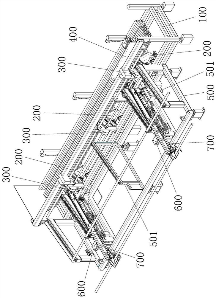
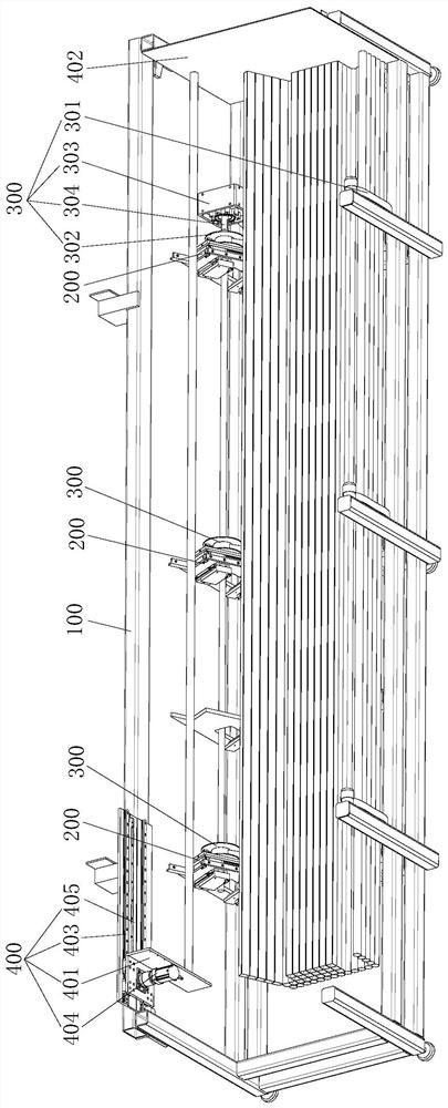
The invention discloses automatic pipe cutting equipment. Through the arrangement of a pipe distributing mechanism, pipes on a pipe warehouse rack can be distributed one by one; through the arrangement of a material transferring and centering mechanism, the pipes can be transferred to the discharging side of a feeding rack, and transverse centering and positioning are achieved; through the arrangement of a feeding and centering mechanism, the pipes on the discharging side of the feeding rack can be vertically centered and positioned and sent out to next equipment; through the arrangement of amaterial supporting mechanism, the pipes conveyed by the feeding and centering mechanism can be stably supported, pipe feeding and cutting are assisted, and the stability of the pipes in the front-section cutting process is guaranteed; and through the arrangement of the material supporting mechanism, the pipes on the discharging side of a cutting machine can be stably supported, pipe feeding and cutting are assisted, and the stability of the pipes in the rear-section cutting process is guaranteed. Thus, the automatic pipe cutting equipment can achieve the procedures of automatic distributing,centering and positioning, feeding, material supporting, material receiving, feeding and cutting and the like of the pipes, and the mechanization degree and the automation degree are high.

Description

technical field [0001] The invention relates to the technical field of mechanical processing, in particular to an automatic pipe material cutting device. Background technique [0002] At present, the machinery industry uses cutting machines to cut pipes to mass-produce pipes of a specific length. In order to achieve the purpose of continuous cutting, it usually uses simple mechanical equipment to realize feeding one by one after manual auxiliary distribution. The feeding operation efficiency is low, and it is easy to have large operation errors, so that the placement position of the pipe material is not accurate, which leads to the accurate clamping of the chuck of the cutting machine. Increased labor costs are not conducive to the improvement of production capacity, and it is easy to cause damage to the health of workers during the work process. Contents of the invention [0003] The object of the present invention is to provide an automatic pipe material cutting device ...

Claims


Application Information

Patent Timeline
Patent Type & Authority Applications(China)
IPC IPC(8): B23Q7/00
CPCB23Q7/00
Inventor 梁建冬黄思薪练振达廖谷祥左建林杨红杰严君仪林哲肖冲吴昌坚王红胜
Owner 佛山汇百盛激光科技有限公司
Why Eureka
Try Eureka