Camera shooting optical lens
An optical lens and lens technology, applied in the field of optical lenses, can solve the problems of long focal length, ultra-thinning, optical power, unreasonable lens spacing and lens shape settings, and achieve the effect of excellent optical characteristics
- Summary
- Abstract
- Description
- Claims
- Application Information
AI Technical Summary
Problems solved by technology
Method used
Image

Examples
no. 1 approach )
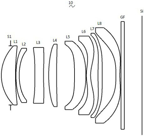
[0032] Referring to the accompanying drawings, the present invention provides an imaging optical lens 10 . figure 1 Shown is a schematic structural view of the imaging optical lens 10 according to the first embodiment of the present invention, and the imaging optical lens 10 includes eight lenses. Specifically, the photographing optical lens 10 includes in sequence from the object side to the image side: an aperture S1, a first lens L1, a second lens L2, a third lens L3, a fourth lens L4, a fifth lens L5, a sixth lens Lens L6, seventh lens L7, and eighth lens L8. An optical element such as an optical filter (filter) GF may be disposed between the eighth lens L8 and the image plane Si.
[0033] In this embodiment, the first lens L1 has a positive refractive power, the second lens L2 has a negative refractive power, the third lens L3 has a negative refractive power, the fourth lens L4 has a positive refractive power, and the fifth lens L5 has a positive refractive power , the ...
no. 2 approach )
[0163] The second embodiment is basically the same as the first embodiment, and the meanings of the symbols are the same as those of the first embodiment, and only the differences are listed below.
[0164] Figure 5 Shown is a schematic structural view of the imaging optical lens 20 according to the second embodiment of the present invention.
[0165] Table 5 and Table 6 show design data of the imaging optical lens 20 according to the second embodiment of the present invention.
[0166] 【table 5】
[0167]
[0168] Table 6 shows the aspheric surface data of each lens in the imaging optical lens 20 according to the second embodiment of the present invention.
[0169] 【Table 6】
[0170]
[0171] Table 7 and Table 8 show the design data of inflection point and stagnation point of each lens in the imaging optical lens 20 according to the second embodiment of the present invention.
[0172] 【Table 7】
[0173]
[0174] 【Table 8】
[0175]
[0176] Figure 6 , Fig...
no. 3 approach )
[0180] The third embodiment is basically the same as the first embodiment, and the meanings of the symbols are the same as those of the first embodiment, and only the differences are listed below.
[0181] Figure 9 Shown is a schematic structural view of the imaging optical lens 30 of the third embodiment of the present invention. In this embodiment, the fourth lens L4 has a negative refractive power, the image side of the first lens L1 is convex at the paraxial position, and the third lens L3 The side of the object is concave near the axis.
[0182] Table 9 and Table 10 show design data of the imaging optical lens 30 according to the third embodiment of the present invention.
[0183] 【Table 9】
[0184]
[0185] Table 10 shows the aspheric surface data of each lens in the imaging optical lens 30 of the third embodiment of the present invention.
[0186] 【Table 10】
[0187]
[0188] Table 11 and Table 12 show the design data of the inflection point and the stagnatio...
PUM
| Property | Measurement | Unit |
|---|---|---|
| Entrance pupil diameter | aaaaa | aaaaa |
| Entrance pupil diameter | aaaaa | aaaaa |
| Entrance pupil diameter | aaaaa | aaaaa |
Abstract
Description
Claims
Application Information
 - R&D
- Intellectual Property
- Life Sciences
- Materials
- Tech Scout
- Unparalleled Data Quality
- Higher Quality Content
- 60% Fewer Hallucinations
Browse by: Latest US Patents, China's latest patents, Technical Efficacy Thesaurus, Application Domain, Technology Topic, Popular Technical Reports.
© 2025 PatSnap. All rights reserved.Legal|Privacy policy|Modern Slavery Act Transparency Statement|Sitemap|About US| Contact US: help@patsnap.com