
Ship

A ship and bow technology, which is applied in hull, icebreaker, ship construction, etc., can solve the problems of increased wave resistance and wave resistance, decreased sailing performance, broken waves, etc., to reduce wave resistance and wave resistance, and improve navigation performance effect

Inactive Publication Date: 2020-11-13
JAPAN MARINE UNITED CORP
View PDF8 Cites 0 Cited by
  • Summary
  • Abstract
  • Description
  • Claims
  • Application Information

AI Technical Summary

Problems solved by technology

Therefore, there is a risk of breaking waves easily caused by the bow, increasing wave resistance and wave resistance, and degrading sailing performance

Method used


Image

  • Ship
  • Ship
  • Ship

Examples


Embodiment approach

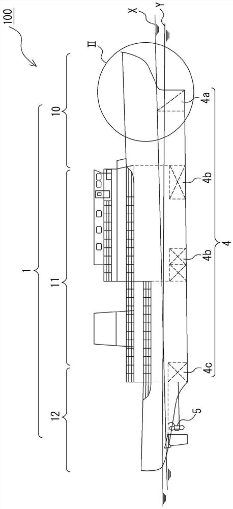
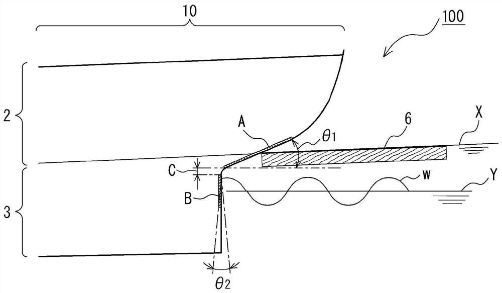
[0026] figure 1 It is an overall view of the ship according to the embodiment of the present invention. figure 2 Yes figure 1 Enlarged view of Part II shown. In this embodiment, an icebreaker will be described as an example of a ship capable of navigating in icy sea areas during marine transportation or marine traffic. In addition, the front in this embodiment means the direction toward a bow, and the rear means a direction toward a stern.

[0027] like figure 1 As shown, the ship 100 of this embodiment has the hull 1 divided by the bow part 10, the hull center part 11, and the stern part 12. The bow portion 10 constitutes the front part of the hull 1 and is configured in a shape that narrows toward the front end. The hull central part 11 has a structure according to the usage. For example, if it is used for marine transportation, a plurality of cabins are formed inside the hull central part 11 . The stern portion 12 constitutes the rear portion of the hull 1 . In the...


PUM


Abstract

This ship comprises a bow portion having: a bow upper portion which has a leading-end surface formed so as to incline rearward toward the bottom and which falls in the draft range during navigation inice-covered waters; and a bow lower portion which has a leading-end surface formed so as to extend straight below from the lower end of the bow upper portion and which falls in the draft range duringnavigation in non-ice-covered waters.

Description

technical field [0001] The invention relates to ships capable of navigating in icy seas. Background technique [0002] As ships capable of navigating in icy sea areas, for example, icebreakers and the like are known. The icebreaker has a bow that narrows toward the front end, and a load in the vertical direction is applied to the bow on board the ice floe, and the icebreaker sails continuously while squeezing and cutting the floe. Therefore, the front end surface of the upper bow portion of the icebreaker is formed in a shape that inclines toward the rear side as it goes downward. In addition, the front end surface of the bow lower part of the icebreaker is formed in such a shape that the side shape of the bow upper part is extended downward in order to disperse the ice flakes to the left and right sides of the hull so that the ice flakes do not sink into the bottom of the ship. The line of has the lower part of the bow. However, when an icebreaker having such a lower bow...

Claims


Application Information

Patent Timeline
Patent Type & Authority Applications(China)
IPC IPC(8): B63B1/06B63B35/08B63B43/06
CPCB63B1/06B63B35/08B63B43/06Y02T70/10B63B11/04B63B2207/02
Inventor 筱原宽山内丰川岛义伸
Owner JAPAN MARINE UNITED CORP
Learn More