A test tube automatic cleaning device for laboratory
An automatic cleaning and inspection technology, which is applied to the cleaning method using liquid, cleaning hollow objects, cleaning methods and utensils, etc., can solve the problems of low degree of automation, low cleaning efficiency, inspection failure, etc., to improve cleaning quality and improve Cleaning efficiency, effect of reducing workload
- Summary
- Abstract
- Description
- Claims
- Application Information
AI Technical Summary
Problems solved by technology
Method used
Image
Examples
Embodiment 1
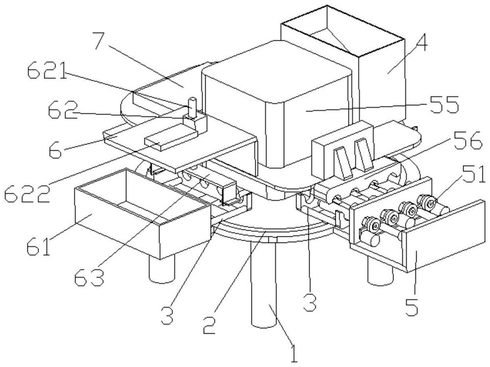
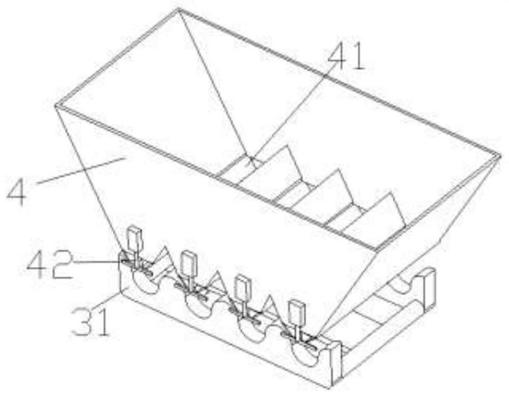
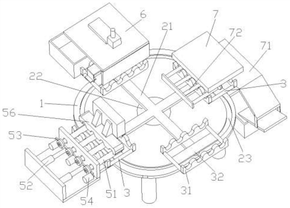
[0022] Embodiment 1: as figure 1 , 2 , shown in 3 and 4, a test tube automatic cleaning device for laboratory, comprising a support frame 1, a cross turntable 2 arranged on the support frame 1, four test tube trays 3 respectively arranged on the cross turntable 2, sequentially Corresponding to the first test tube box 4, the first cleaning unit 5, the second cleaning unit 6, and the test tube collection unit 7 arranged above the four test tube trays 3, it is used to control the cross turntable 2, the first cleaning unit 5, and the second cleaning unit 6. The controller of the test tube collection unit 7;
[0023] The cross turntable 2 includes a cross rotation member 21 movably arranged on the support frame 1, a servo motor 22 provided on the support frame 1 to provide power for the cross rotation member 21, an annular guide rail 23 arranged on the support frame 1; 4 test tube trays 3 are respectively arranged at the four ends of the cross rotating member 21;
[0024] The te...
Embodiment 2
[0034] Embodiment 2: Different from Embodiment 1, as Figure 5 As shown, the mechanical grip 62 includes a motor worm 621, a second telescopic motor 622 fixed on the second box for controlling the sliding of the motor worm 621, and a gripper 63 that can grab the test tube tray 3 at the lower end of the motor worm 621.
[0035] Such as Figure 6 As shown, the gripper 63 includes a gripper support 631, two grippers 632 hinged at both ends of the gripper support 631, two grippers with one end hinged to the gripper 632 and one end slidably disposed on the gripper support 631 The connecting rod 633 is arranged on the handle support member 631 and can control the motor rack of the two handle connecting rods 633 to slide.
[0036] Such as Figure 7 As shown, the electric valve 42 includes a valve 421 that is hinged at the test tube outlet 41 at one end, and a linear motor 422 that controls the opening and closing of the other end of the valve 421; there are two valves 421; groove....
PUM
 Abstract
Description
Claims
Application Information
 - R&D
- Intellectual Property
- Life Sciences
- Materials
- Tech Scout
- Unparalleled Data Quality
- Higher Quality Content
- 60% Fewer Hallucinations
Browse by: Latest US Patents, China's latest patents, Technical Efficacy Thesaurus, Application Domain, Technology Topic, Popular Technical Reports.
© 2025 PatSnap. All rights reserved.Legal|Privacy policy|Modern Slavery Act Transparency Statement|Sitemap|About US| Contact US: help@patsnap.com


