Compound continuous stepped spillway and implementation method thereof
A spillway and ladder technology, which is applied in water conservancy projects, sea area engineering, coastline protection, etc., can solve the problems that the steady flow and energy dissipation rate of stepped spillways cannot meet the requirements of flood discharge energy dissipation, spillway damage, etc., so as to avoid cavitation damage and ensure The effect of safe operation
- Summary
- Abstract
- Description
- Claims
- Application Information
AI Technical Summary
Problems solved by technology
Method used
Image

Examples
Embodiment 1
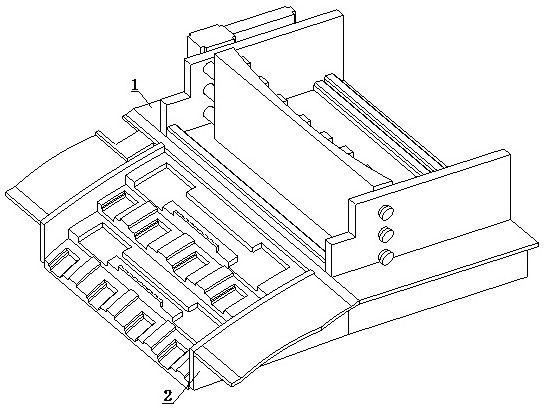
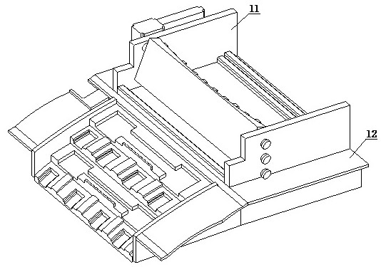
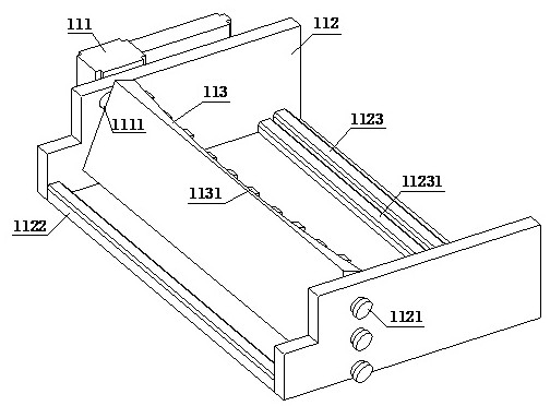
[0036] refer to Figure 1-3, a compound continuous stepped spillway, including a flood inlet mechanism 1 and a flood overflow mechanism 2, the outlet end of the flood inlet mechanism 1 is connected to the overflow mechanism 2, the flood inlet mechanism 1 includes a flood inlet gate assembly 11 and a bearing surface 12, and the flood inlet gate The assembly 11 is installed on the upper end surface of the bearing surface 12, and the flood gate assembly 11 is composed of a rotating motor 111, a splint 112 and an arc gate 113. A rotating motor 111 is arranged on one side of the splint 112, and the output end of the rotating motor 111 The arc gate 113 is connected through the drive shaft 1111, and the side of the bearing surface 12 close to the arc gate 113 is connected with a flood mechanism 2; Several cushion blocks 1131 are arranged on the arc surface of the arc gate 113, and a rotating rod 1132 is installed on the side of the arc gate 113 close to the sleeve 1121. The other end...
Embodiment approach
[0038] In order to better demonstrate the implementation process of the compound continuous stepped spillway, this embodiment now proposes an implementation method of the compound continuous stepped spillway, including the following steps:
[0039] Step 1: At the beginning of flood discharge, the water flow passes through the first water inlet stopper 1123 and the second water inlet stopper 11231 in sequence and contacts the inner side of the arc gate 113, and at the same time starts the rotating motor 111, and uses the drive shaft 1111 to rotate the arc gate 113 To a certain angle or when the water flow rate is large, do not start the rotating motor 111 and directly use the square water channel 1133 to drain water, and make the water flow pass through the first water inlet block 1123 and discharge into the overflow side wall 22;
[0040] Step 2: After the water flow enters the spillway side wall 22, it first flows into the first-level energy dissipation tank 2211 of the upper ...
Embodiment 2
[0046] refer to Figure 7-8 , a compound continuous stepped spillway, including a flood inlet mechanism 1 and a flood overflow mechanism 2, the outlet end of the flood inlet mechanism 1 is connected to the overflow mechanism 2, the flood inlet mechanism 1 includes a flood inlet gate assembly 11 and a bearing surface 12, and the flood inlet gate The assembly 11 is installed on the upper end surface of the bearing surface 12, and the flood gate assembly 11 is composed of a rotating motor 111, a splint 112 and an arc gate 113. A rotating motor 111 is arranged on one side of the splint 112, and the output end of the rotating motor 111 The arc gate 113 is connected through the drive shaft 1111, and the side of the bearing surface 12 close to the arc gate 113 is connected with a flood mechanism 2; Several cushion blocks 1131 are arranged on the arc surface of the arc gate 113, and a rotating rod 1132 is installed on the side of the arc gate 113 close to the sleeve 1121. The other en...
PUM
 Abstract
Description
Claims
Application Information
 - Generate Ideas
- Intellectual Property
- Life Sciences
- Materials
- Tech Scout
- Unparalleled Data Quality
- Higher Quality Content
- 60% Fewer Hallucinations
Browse by: Latest US Patents, China's latest patents, Technical Efficacy Thesaurus, Application Domain, Technology Topic, Popular Technical Reports.
© 2025 PatSnap. All rights reserved.Legal|Privacy policy|Modern Slavery Act Transparency Statement|Sitemap|About US| Contact US: help@patsnap.com