Digital variable hydraulic motor radial plunger pump

A hydraulic motor and digital variable technology, which is applied in variable capacity pump components, liquid variable capacity machines, liquid fuel engines, etc., can solve volumetric efficiency, low overall efficiency, large overall volume and weight, and many parts/components, etc. problem, to achieve the effect of large displacement adjustable range, good power adaptability and small energy loss

Active Publication Date: 2020-11-17
LANZHOU UNIVERSITY OF TECHNOLOGY
View PDF12 Cites 0 Cited by
  • Summary
  • Abstract
  • Description
  • Claims
  • Application Information

AI Technical Summary

Problems solved by technology

[0003] Summarize the above technical deficiencies: 1. There are many parts / components involved, and the structure is relatively complicated; 2. The motor is cooled by air cooling, which has a lot of noise, or water-cooled / oil-cooled motors, but additional cooling systems are required, which increases the complexity of the system 3. There is insufficient oil absorption, especially at high speeds, resulting in low volumetric efficiency and low overall efficiency
4. The friction pair between the rotor and the plunger is not lubricated by oil, and the friction and wear are relatively large; 5. The bearing can only be sealed by grease, and its life is limited; 6. There is external leakage at the shaft seal, which may cause potential risks of polluting the environment; 7. Connection with the motor Couplings are still required, the axial dimension is still large, and the overall volume and weight are large

Method used


Image

  • Digital variable hydraulic motor radial plunger pump
  • Digital variable hydraulic motor radial plunger pump
  • Digital variable hydraulic motor radial plunger pump

Examples


Embodiment Construction

[0020] The principles and features of the present invention are described below in conjunction with the accompanying drawings, and the examples given are only used to explain the present invention, and are not intended to limit the scope of the present invention.

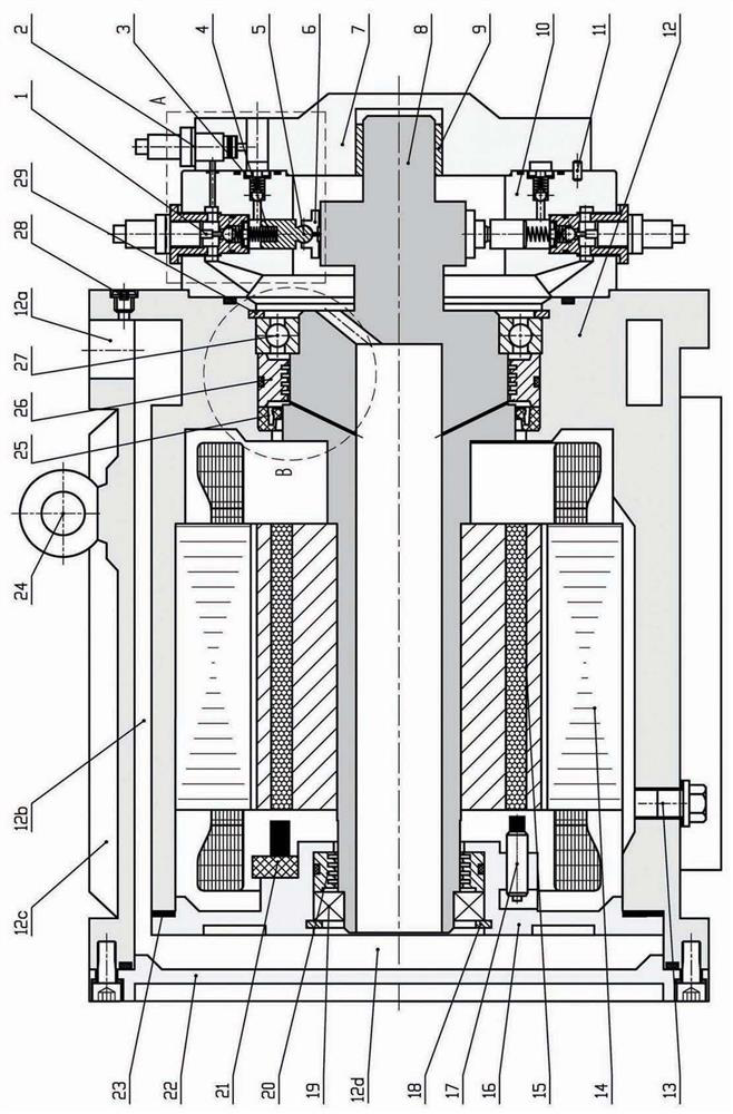
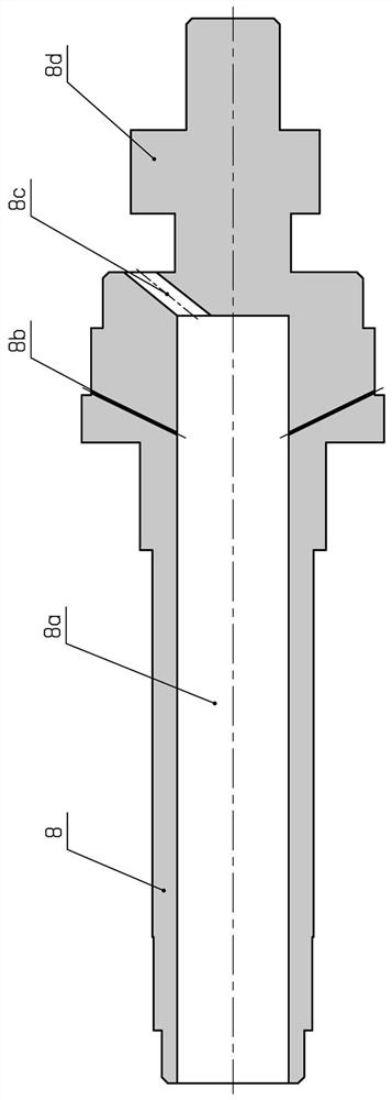
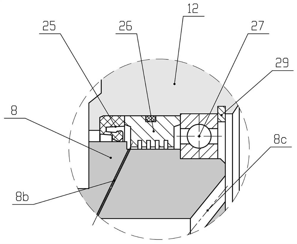
[0021] Such as Figure 1~Figure 7 As shown, the present invention is a digital variable hydraulic motor radial piston pump, which integrates a permanent magnet motor, a radial piston pump, a liquid-filled centrifugal pump, a digital switch valve and a safety valve, including a digital switch Oil suction check valve 1, safety valve 2, oil discharge check valve 3, return spring 4, ball plunger 5, sliding shoe 6, front end cover 7, hollow composite shaft 8, sliding bearing 9, pump body 10, positioning pin 11. Housing 12, oil drain plug 13, motor stator 14, motor rotor 15, inner end cover 16, speed sensor 17, first spring retaining ring 18, first bearing 19, first sealing ring 20, position sensor 21 , Rear end cover 22...


PUM


Abstract

The invention discloses a digital variable hydraulic motor radial plunger pump. A motor rotor (15) is arranged on a hollow composite shaft (8) in a hot sleeving mode and supported in a shell (12) through bearings (19 and 27), and a sealing ring (20), a sealing ring (26) and a lip-shaped sealing ring (25) are arranged on the two sides of each bearing; a ball plunger (5) and a sliding shoe (6) are rolled into a whole and are in spherical hinge connection, the axis of the ball plunger (5) is perpendicular to the axis of the hollow composite shaft (8), the sliding shoe (6) is in contact fit with an eccentric disc (8c) on the hollow composite shaft (8), and when the eccentric disc (8c) rotates along with the hollow composite shaft (8), the ball plunger (5) and the sliding shoe (6) are driven tomove in corresponding plunger holes (10c) formed in a pump body (10) and reset under the action of a reset spring (4); and the axis of a digital switch oil suction one-way valve (1) coincides with the axes of the plunger holes (10c), and an oil discharge one-way valve (3) is arranged perpendicular to an electromagnetic switch oil suction one-way valve (1).

Description

technical field [0001] The invention relates to electro-hydraulic integrated hydraulic power unit technology, in particular to a digital variable hydraulic motor radial plunger pump. Background technique [0002] The electro-hydraulic integrated hydraulic power unit is a new development direction of hydraulic power equipment, and it has developed rapidly in the international and domestic markets due to its huge advantages such as low noise, high efficiency, compact structure, and man-machine friendliness. At present, the technology mainly focuses on the integration of quantitative hydraulic pump and electric motor, such as the hydraulic motor vane pump of Eaton in the United States, the electro-hydraulic integrated helical gear pump of Rexroth in Germany, and the air gap non-immersed hydraulic motor vane pump developed by Lanzhou University of Technology, etc. . In occasions with high working pressure or even ultra-high pressure and strict requirements on axial dimensions, ...

Claims


Application Information

Patent Timeline
IPC IPC(8): F04B17/03F04B1/053F04B1/06F04B1/0456F04B1/0448F04B1/0408F04B53/08F04B53/18F04B53/00F04B53/22F04B49/20
CPCF04B1/0408F04B1/0448F04B1/0456F04B1/053F04B1/06F04B17/03F04B49/20F04B53/001F04B53/08F04B53/18F04B53/22
Inventor 冀宏孙为汤荣福刘耀卓白宇杰闵为邢晖晖
Owner LANZHOU UNIVERSITY OF TECHNOLOGY
Why Eureka
Try Eureka