Sewage evaporative air cooler

An evaporative and air cooler technology, applied in water shower coolers, direct contact heat exchangers, heat exchanger types, etc., can solve problems such as waste of fresh water resources, reduce scaling, reduce adhesion, and improve flushing effect Effect

Pending Publication Date: 2020-11-17
重庆天瑞化工设备股份有限公司 +1
0 Cites 0 Cited by

AI-Extracted Technical Summary

Problems solved by technology

[0003] The present invention intends to provide a sewage evaporative air cooler to solve the problem of waste of ...

Method used

Start the dosing pump while starting the pump 4, so that the dosing pump imports the scale inhibitor in the connecting pipe, and then makes the scale inhibitor enter the catheter tube synchronously...

Abstract

The invention belongs to the technical field of equipment contacting heat exchange through multiple media, and discloses a sewage evaporative air cooler which comprises an equipment main body, a plurality of groups of heat exchange coils are arranged in the equipment main body, the equipment main body is further provided with an air inlet, a spraying system and an air outlet, and the air inlet andthe spraying system are both located at the top of the equipment main body; and the spraying system comprises a plurality of flow guide pipes, the flow guide pipes are provided with a plurality of spray heads in a communicating mode, and each flow guide pipe communicates with a sewage pipe. The problem that fresh water resources are wasted due to the fact that fresh water is used as circulating make-up water of an evaporative air cooler at present is solved.

Application Domain

Technology Topic

SewageContact heat +4

Image

  • Sewage evaporative air cooler
  • Sewage evaporative air cooler
  • Sewage evaporative air cooler

Examples

  • Experimental program(2)

Example Embodiment

[0041] Example 1:
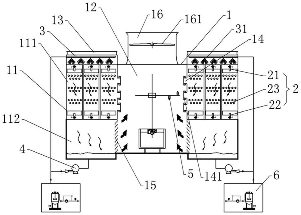
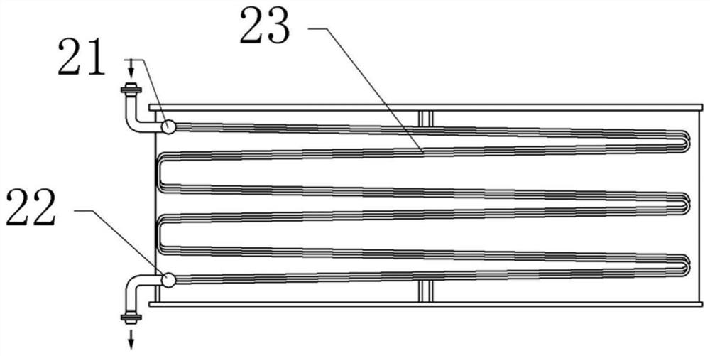
[0042] Sewage evaporative air cooler, basically as attached figure 1 As shown, it includes an equipment main body 1. The equipment main body 1 is provided with two cooling parts 11 and an air duct 12 located between the two cooling parts 11. The top of the equipment main body 1 is provided with an air outlet 16 that communicates with the air duct 12. An impeller 161 is provided in the air outlet 16 . The cooling part 11 includes an upper cooling layer 111 and a lower collection layer 112, the cooling layer 111 and the collection layer 112 are connected, the cooling layer 111 is isolated from the air duct 12, and a plurality of groups of heat exchange coils 2 are arranged in the cooling layer 111, In this embodiment, three sets of heat exchange coils 2 arranged laterally are provided, and the three sets of heat exchange coils 2 are independently arranged. combine figure 2 As shown, the heat exchange coil 2 includes a medium inlet 21 , a small coil 23 and a medium outlet 22 arranged in sequence from top to bottom, and two ends of the small coil 23 communicate with the medium inlet 21 and the medium outlet 22 respectively. The surface roughness of the heat exchange coil 2 is Ra0.05˜Ra0.2, and in this embodiment, the surface roughness is preferably Ra0.1.
[0043] The top of the cooling layer 111 is also provided with an air inlet 13 and a spray system. When in use, the air inlet 13 is communicated with the induced draft fan, so that the air generated by the induced draft fan is introduced into the cooling layer 111 through the air inlet 13 . The air outlet end of the air inlet 13 faces downward, so that the air can flow from top to bottom. The sprinkler system includes a plurality of guide pipes 3 arranged laterally, both ends of the guide pipes 3 are closed, and the guide pipes 3 are arranged side by side along the direction perpendicular to the paper surface, and the number of the guide pipes 3 is determined according to actual needs. set, in this embodiment, three are set. The bottom end of the guide pipe 3 is provided with a plurality of spray heads 31 , and the liquid outlet direction of the spray heads 31 is downward. The spray system also includes a sewage pipe that communicates with the guide pipe 3. When in use, the sewage pipe is connected to the liquid inlet pump, so that the sewage can be introduced into the cooling layer 111 for use.
[0044] The opposite sides of the cooling layers 111 of the two cooling parts 11 are provided with a plurality of flushing ports 14 . The number of the flushing ports 14 is selected according to actual needs. In this embodiment, there are three flushing ports 14 . A movable air plate 141 can be detachably connected to the flushing port 14. The removable connection between the movable air plate 141 and the flushing port 14 can be threaded connection or clip connection. In this embodiment, a threaded connection is selected.
[0045] A water collector is provided on the opposite side of the collection layer 112, combined with image 3 As shown, the water collector 15 includes mounting bars 151 fixed on the front and rear sides of the collection layer 112 and a plurality of corrugated plates 152 fixed between the two mounting bars. An air guide channel is formed between the adjacent corrugated plates 152, and the corrugated plates 152 are evenly arranged in the vertical direction, and the corrugated plates 152 are inclined upward in the direction close to the air duct. The outer side of the convex portion of the corrugated plate 152 is fixed with an arc-shaped guide strip 153 .
[0046] The bottom of the collection layer 112 is connected with a water outlet pipe, the water outlet pipe is connected with the suction pump 4, and the water outlet end of the suction pump 4 is connected with a communication pipe, and the end of the communication pipe away from the suction pump 4 is connected with the guide pipe 3.
[0047] The air duct 12 is also provided with a high-pressure flushing system. The high-pressure flushing system includes an installation frame, a sliding frame vertically slidably connected to the installation frame, and a mounting block laterally slidably connected to the sliding frame. Two high-pressure spray heads 5 are fixed on the installation block. , the spraying direction of one of the high-pressure nozzles 5 is upward, and the spraying direction of the other high-pressure nozzle 5 is downward.
[0048] It also includes a water conduit connected with the two high-pressure spray heads 5 respectively. When in use, the water conduit is connected with the water pump, so that water can be guided into the high-pressure spray head 5, thereby realizing the flushing of the heat exchange coil 2.
[0049] It also includes two medicine dosing devices, each of which includes a medicine storage box, and a medicine addition pipe is connected to the two medicine storage boxes, and the medicine addition pipe is communicated with the communication pipe. The medicine adding box 6 is filled with a scale inhibitor, and a liquid filling port is also provided on the medicine adding box 6 . The medicine storage box is provided with a medicine dosing pump which is communicated with the medicine dosing pipe.
[0050] The specific implementation process is as follows:
[0051] The process medium to be cooled is introduced from the medium inlet 21 of the heat exchange coil 2 and flows down along the heat exchange coil 2. During the flow of the process medium to be cooled, the induced draft fan and the liquid feed pump are started, so that the The induced draft fan introduces air for cooling into the air inlet 13, and the air flows downward; the liquid inlet pump introduces sewage into the flow pipe 3 through the sewage pipe, and also flows downward through the spraying place of the nozzle 31. The sprayed sewage forms a water film on the outer wall of the heat exchange coil 2, and the process medium in the heat exchange coil 2 transfers heat to the water film, so that the water film evaporates rapidly and cools the process medium. After the air is in contact with the heat exchange coil, heat exchange is also carried out to achieve cooling of the process medium.
[0052] During this process, since both air and sewage flow from top to bottom, heat exchange with the process medium in the heat exchange coil 2 can continue during the flow, thereby improving the cooling effect.
[0053] Since the air and sewage flow downward synchronously, the potential energy of the downward flow is greater. When the impurities in the sewage adhere to the heat exchange coil 2, they will be flushed by the subsequent air and sewage to reduce the amount of adhesion. In addition, due to the large potential energy of sewage flowing downward, and the small surface roughness of the outer wall of the heat exchange coil 2, the amount of impurities attached to the heat exchange coil 2 itself is less, which can reduce the junction of the outer wall of the heat exchange coil 2. dirt.
[0054] After the sewage and air flow downward and conduct heat exchange, they will gradually flow into the collection layer 112 and be collected through the collection layer 112 . After the air pressure in the collection layer 112 is high, the water vapor generated by the air and heat exchange will flow along the air guide channel formed between the corrugated plates 152 , enter the air channel 12 , and then flow upward along the air channel 12 . , discharged from the air outlet 16 . During this process, since the temperature in the collection layer 112 is lower than that of the cooling layer, and the water vapor will condense after contacting the corrugated plate 152 to form a liquid, and the droplets flow along the inclined corrugated plate 152 and enter the collection layer 112 It is collected inside, which is convenient for subsequent recycling.
[0055] After the heat-exchanged sewage accumulates in the collection layer 112, since the collection layer 112 is far away from the heat exchange coil 2, the sewage accumulated in the collection layer 112 will gradually cool down, and after a certain amount of sewage is accumulated, the pump 4 is started, The sewage in the collection layer 112 is introduced into the guide pipe 3 by the suction pump 4, and then sprayed out from the nozzle 31, so that the reuse of the sewage can be completed.
[0056] When starting the suction pump 4, start the dosing pump, so that the dosing pump introduces the scale inhibitor into the communication pipe, so that the scale inhibitor enters the liquid conduit synchronously with the sewage, and then sprays out, and the scale inhibitor is sprayed on the heat exchange coil. On the outer wall of the heat exchange coil 2, the scaling of the heat exchange coil 2 can be reduced.
[0057] When the evaporative air cooler has been used for a long time, open the movable air plate 141 and move the high-pressure nozzle 5 so that the high-pressure nozzle 5 extends into the flushing port 14, turn on the water pump, and extract fresh water to flush the heat exchange coil 2, thereby completing the The impurities and soft scales on the outer wall of the heat exchange coil 2 are washed away to avoid long-term accumulation and the occurrence of scaling on the outer wall of the heat exchange coil 2 . By moving the carriage vertically and moving the high-pressure nozzle 5 laterally along the carriage, the position of the high-pressure nozzle 5 can be adjusted, thereby increasing the flushing range and fully cleaning the heat exchange coil 2 .

Example Embodiment

[0058] Example 2:
[0059] Example 2 differs from Example 1 only in that, as Figure 4 As shown, in this embodiment, a filter device is arranged in the collection layer 112, and the filter device includes a rotating shaft 8 arranged in the collection layer 112. The rotating shaft 8 is provided with a material guide flow channel 81, and the material guide flow channel 81 is communicated with the outside, and the guide flow channel 81 is connected to the outside. The flow channel is tapered, and the large diameter end of the guide channel communicates with the outside.
[0060] The rotating shaft 8 penetrates through the rear side of the collection layer 112 , and the rotating shaft 8 is rotatably connected to the collection layer 112 . A plurality of collecting plates 9 are evenly distributed on the outer wall of the rotating shaft 8 , and the number of collecting plates 9 can be selected according to actual requirements. In this embodiment, there are five collecting plates 9 . The collecting plates 9 each include a U-shaped plate body 91 and a filter screen 92 fixed on the top of the upper vertical part of the plate body 91 , and the upper surface of the filter screen 92 is flush with the upper surface of the plate body 91 .
[0061] The specific structure of the collecting plate 9 is described with the collecting plate 9 on the right. The plate body 91 is provided with an L-shaped material guide groove 911, and the left end of the material guide groove 911 penetrates the plate body 91; 911 and the through groove 82 of the material guide channel 81; the top end of the material guide groove 911 penetrates the vertical part of the right side of the plate body 91.
[0062] combine Figure 5 As shown, the right end of the plate body 91 is also fixed with a stopper 912, the bottom of the stopper 912 is provided with a sliding hole, and a baffle 913 is slidably connected in the sliding hole. It is in contact with the upper surface of the board body 91 . A push block 914 is fixed on the left end of the baffle 913, a spring is arranged between the push block 914 and the stop 912, and both ends of the spring are welded to the right end face of the push block 914 and the left end face of the stop 912; An anti-disconnection block 915 is fixed on the right end.
[0063] The collecting layer 112 is provided with a blocking plate 7, the outer periphery of the blocking plate 7 is welded on the inner wall of the top end of the collecting layer 112, the blocking plate 7 is provided with an outlet 71, and the outlet 71 is located on the side of the blocking plate 7 away from the air duct 12, And the outlet 71 is inclined from top to bottom toward the direction close to the air duct 12 .
[0064] A first magnetic block is fixed on the bottom of the collection layer 112 , and a second magnetic block mutually repelling the first magnetic block is provided on the anti-separation block 915 .
[0065] The specific implementation process is as follows:
[0066] During the operation of the sewage evaporative air cooler, after heat exchange with the process medium to be cooled, sewage and air are blocked by the blocking plate 7, and then introduced into the collection layer 112 through the outlet 71 on the blocking plate 7. During this process, due to the collection of air and sewage through the outlet 71, the flow velocity is relatively large, and the outlet 71 is inclined, so that the air and sewage can impact the collecting plate 9, thereby causing the collecting plate 9 to rotate, thereby driving the rotating shaft 8 to rotate, Continuous rotation of the collecting plate 9 on the entire rotating shaft 8 is achieved. Moreover, due to the location of the outlet 71, the rotating shafts 8 in the two collection layers 112 will rotate relative to each other, and the collection layer 112 on the left side rotates clockwise, and the collection layer 112 on the right side rotates counterclockwise. Avoid raising the collected sewage into the air duct 12 through the outlet 71 .
[0067] The sewage after heat exchange will contain impurities. At the same time, if it is used for a long time, some soft scale will be formed on the outer wall of the heat exchange coil 2. Under the washing of air and water during use, the soft scale will flow with the air and sewage. In order to avoid impurities When the sewage is recycled, and the soft scale adheres to the heat exchange coil 2, resulting in an increase in the scale of the heat exchange coil 2, the impurities are filtered and collected by setting the collection layer 112.
[0068]The air and water impinge on the filter screen 92 on the collecting plate 9, the impurities and soft dirt are filtered through the filter screen 92, and the filtered water flows to the collecting layer 112 through the gap between the filter screen 92 and the plate body 91 Bottom, then impurities and soft scale remain on the screen 92. With the rotation of the rotating shaft 8 and the collecting plate 9 , the collecting plate 9 is gradually inclined, so impurities and soft dirt will move along the inclined filter screen 92 . During the tilting process of the collecting plate 9, the baffle 913, the push block 914 and the anti-detachment block 915 will gradually slide down under the action of gravity, and squeeze the spring, so that the baffle 913 slides over the blocking guide groove 911, so that the After finishing, the impurities and impurities enter the material guide trough 911 .
[0069] As the rotating shaft 8 and the collecting plate 9 continue to rotate, the collecting plate 9 with collected impurities will be brought close to the bottom surface of the collecting layer 112, and the first magnet block and the second magnet block will gradually approach during this process, so that the first magnet block will be repelled. With the second magnetic block, the baffle 913 slides upward to close the material guide groove 911 to prevent impurities and soft dirt from falling out, and at the same time, it can also prevent sewage from entering the material guide groove 911 .
[0070] During the continuous rotation of the rotating shaft 8 and the collecting plate 9, the collecting plate 9 gradually moves away from the sewage collected in the collecting layer 112. When the collecting plate 9 is tilted again, the impurities and soft dirt in the guide groove 911 enter along the guide groove 911. The material flows in the guide flow channel 81, and flows along the guide flow channel 81, and is discharged. The amount of impurities in the sewage in the collection layer 112 is reduced, thereby reducing the occurrence of increased scaling on the heat exchange coil 2 when the sewage in the collection layer 112 is recycled for use.

PUM

no PUM

Description & Claims & Application Information

We can also present the details of the Description, Claims and Application information to help users get a comprehensive understanding of the technical details of the patent, such as background art, summary of invention, brief description of drawings, description of embodiments, and other original content. On the other hand, users can also determine the specific scope of protection of the technology through the list of claims; as well as understand the changes in the life cycle of the technology with the presentation of the patent timeline. Login to view more.

Similar technology patents

Medical flushing device for paralyzed patient nursing

PendingCN113558513AImprove flushing effectReduce spillsBathroom accessoriesMedical transportPatient careEngineering
Owner:HUZHOU TEACHERS COLLEGE

Impurity removing equipment for main food materials of sauced meat

PendingCN114223702AImprove flushing effectImprove practical performanceMoving filtering element filtersMeat processing devicesWorm driveAC - Alternating current
Owner:新晃老蔡食品有限责任公司

Classification and recommendation of technical efficacy words

  • Improve flushing effect
  • Improve heat transfer capacity

Deburring process and deburring equipment for circuit board

Owner:深圳市航盛电路科技股份有限公司

Organic phase change thermal storage material and preparation method thereof

InactiveCN105018038AImprove heat transfer capacityImprove cold and heat storage functionHeat-exchange elementsPhase-change materialStorage material
Owner:SHANGHAI AIR PAQ CO LTD
Why Eureka
Try Eureka