Eureka AIR delivers breakthrough ideas for toughest innovation challenges, trusted by R&D personnel around the world.

Optical trap-based particle shape and surface roughness detection device and method

A surface roughness and detection device technology, which is applied in the direction of measuring devices, optical devices, instruments, etc., can solve problems such as difficult to achieve high-precision measurement

Active Publication Date: 2020-11-17
ZHEJIANG UNIV
View PDF7 Cites 2 Cited by
  • Summary
  • Abstract
  • Description
  • Claims
  • Application Information

AI Technical Summary

Problems solved by technology

In these optical trap measurement devices, the measurement of physical quantities is often accomplished by measuring the particle scattering light field, and the distribution of the scattering light field is related to the particle shape and surface roughness. Therefore, if the particle shape or surface roughness cannot be measured It is difficult to achieve high-precision measurement

Method used


Image

  • Optical trap-based particle shape and surface roughness detection device and method
  • Optical trap-based particle shape and surface roughness detection device and method

Examples


Embodiment Construction

[0023] The present invention will be further elaborated below in conjunction with the accompanying drawings and embodiments.

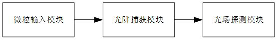
[0024] refer to figure 1 , a high-sensitivity optical trap measurement device, including three modules: a particle input module, an optical trap capture module, and an optical field detection module;

[0025] When it is necessary to detect particles, first turn on the optical trap capture module, collimate and focus the light beam, so that the initial captured light can form the optical trap balance point. After completing the preparations above, you can open the particle input module, transport the particles to be detected to the optical trap capture area, use the optical trap capture module to stably capture the particles at the balance point of the optical trap, and then open the light field detection module, use the collimation The lens collects light scattered by the particle, thereby obtaining information on the shape and surface roughness of th...


PUM


Abstract

The invention discloses a particle shape and surface roughness detection device and method based on an optical trap. The device comprises a particle input module, an optical trap capture module and anoptical field detection module. The particle input module is a device for storing to-be-detected particles and conveying the to-be-detected particles into the light trap field, when the to-be-detected particles are captured by the light trap capture module, the capture light field interacts with the particles, the particles are suspended in the light trap field, and due to the fact that the microspheres and the surrounding environment have different refractive indexes, the particles change the transmission track of the light field. In the process, different transmission fields and reflectionfields are caused by different microsphere shapes and surface roughness, the acted light field is transmitted to the light field detection module, and the information of the microsphere shapes and thesurface roughness can be obtained by detecting and analyzing the transmitted or scattered light beams. According to the invention, the particle surface morphology can be detected under various environmental conditions such as liquid, air or vacuum, and the selection of spherical particles is realized.

Description

technical field [0001] The invention relates to a device and method applied to the detection of particle shape and surface roughness, especially the measurement of microsphere shape by using the interaction between light and matter. Background technique [0002] According to quantum theory, a light beam is a group of photons that move at the speed of light and have both mass and momentum. When the photons are incident on the surface of the medium, refraction and reflection will occur, and the speed and direction of the photons will change, resulting in a change in their momentum vector. The conservation law can be deduced that when the beam irradiates the particle, the momentum change of the photon is equal to the momentum change of the particle, so the beam has a mechanical effect on the particle, which is called the optical radiation pressure, and the optical radiation pressure includes the scattering along the beam propagation direction Under the action of these two force...

Claims


Application Information

Patent Timeline
Patent Type & Authority Applications(China)
IPC IPC(8): G01B11/24G01B11/30
CPCG01B11/24G01B11/30
Inventor 李文强李楠胡慧珠舒晓武刘承
Owner ZHEJIANG UNIV
Why Eureka
Eureka Blog
Learn More