An automatic temperature control tool for optomechanical detection and its use method

An automatic temperature control and optical-mechanical technology, applied in measuring devices, optical instrument testing, machine/structural component testing, etc., can solve problems such as maintaining the normal and stable temperature of the light source, so as to improve the output of optical-mechanical products and ensure the quality of optical-mechanical products Effect

Active Publication Date: 2022-04-12
南阳南方智能光电有限公司
View PDF14 Cites 0 Cited by
  • Summary
  • Abstract
  • Description
  • Claims
  • Application Information

AI Technical Summary

Problems solved by technology

However, this invention also fails to keep the light source at a normal and stable temperature during optical-mechanical detection, and fails to solve the above-mentioned technical problems

Method used


Image

  • An automatic temperature control tool for optomechanical detection and its use method
  • An automatic temperature control tool for optomechanical detection and its use method
  • An automatic temperature control tool for optomechanical detection and its use method

Examples


Embodiment 1

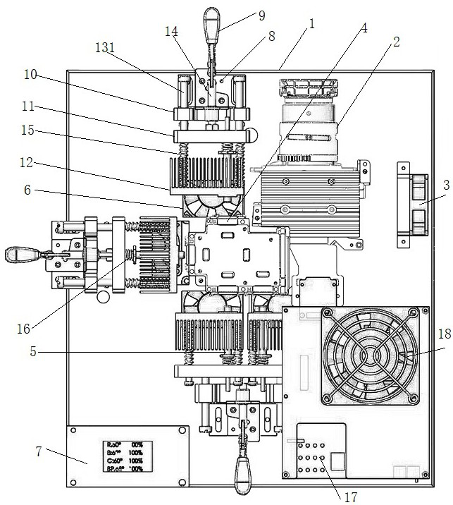
[0034] like Figure 3~4 As shown, an automatic temperature control tool for optomechanical detection includes a stage 1, an optomechanical 2, an optomechanical drive unit, and an optomechanical cooling fan 3. The optomechanical 2 has a plurality of LED light sources 4, and a plurality of A temperature control unit is arranged on the outside of the LED light source 4, and the temperature control unit includes a temperature measuring frame, a temperature sensor 5, a cooling fan 6 and a temperature control module 7, and the temperature sensor 5 is arranged on the temperature measuring frame. The probe of the temperature sensor 5 is in contact with the copper substrate of the LED light source 4 during measurement, the temperature sensor 5 is connected to the input end of the temperature control module through a signal line, and the cooling fan 6 is connected to the output of the temperature control module. The terminals are connected by signal lines.

[0035] Specifically, the te...

Embodiment 2

[0040] like Figure 3~4 As shown, an automatic temperature control tool for optomechanical detection includes a stage 1, an optomechanical 2, an optomechanical drive unit, and an optomechanical cooling fan 3. The optomechanical 2 has a plurality of LED light sources 4, and a plurality of A temperature control unit is arranged on the outside of the LED light source 4, and the temperature control unit includes a temperature measuring frame, a temperature sensor 5, a cooling fan 6 and a temperature control module 7, and the temperature sensor 5 is arranged on the temperature measuring frame. The probe of the temperature sensor 5 is in contact with the copper substrate of the LED light source 4 during measurement, the temperature sensor 5 is connected to the input end of the temperature control module through a signal line, and the cooling fan 6 is connected to the output of the temperature control module. The terminals are connected by signal lines.

[0041] Specifically, the te...

Embodiment 3

[0051] like Figure 6~7 As shown, the difference between the automatic temperature control tooling for optical-mechanical detection in this embodiment of the present invention and Embodiments 1 and 2 is that the temperature control module reads R / G / B / BP respectively through four DS18B20 temperature sensors. Based on the temperature of the backplane of the light source, the cooling fans corresponding to R / G / B / BP are controlled respectively based on the temperature, and then the exhaust air volume is controlled to control the temperature of the backplane of the light source transmitted on the copper block of the tooling, and finally the backplane of the light source is stabilized. Temperature purpose (for example: R temperature 52°C±3, G temperature 62°C±3, B temperature 58°C±3, BP temperature 65°C±3). In order to facilitate the operation of workers, indicator lights of different colors relative to the light source and a TFT liquid crystal temperature display are added to the de...


PUM


Abstract

The invention discloses an automatic temperature control tool for opto-mechanical detection and a method for using it, belonging to the field of opto-mechanical testing. LED light sources, a temperature control unit is arranged on the outside of a plurality of the LED light sources, and the temperature control unit includes a temperature measurement frame, a temperature sensor, a cooling fan and a temperature control module, the temperature sensor is arranged on the temperature measurement frame, and the The probe of the temperature sensor is in contact with the copper substrate of the LED light source during measurement, the temperature sensor is connected to the input end of the temperature control module through a signal line, and the cooling fan is connected to the output end of the temperature control module through a signal line line connection. The present invention can maintain the opto-mechanical detection at a stable temperature, ensure high yield of the opto-mechanical product, and is convenient to operate.

Description

technical field [0001] The invention relates to the field of optical-mechanical detection, in particular to an automatic temperature control tool for optical-mechanical detection and a use method. Background technique [0002] In the production process of the optical machine, it is necessary to test the performance of all aspects of the optical machine, and in the testing process, it is necessary to strictly control the temperature of the copper substrate of the optical machine LED light source (R light source, G light source, B light source, BP light source) within a certain range , if the temperature control is not good, it will cause the color cast of the light source, the color coordinates will be incorrect, and it may even cause the light source to burn out due to excessive temperature. Because the light effect, life and temperature of the LED chip light source are very closely related, and a reasonable working temperature can ensure that the LED light source can be use...

Claims


Application Information

Patent Timeline
Patent Type & Authority Patents(China)
IPC IPC(8): G01M11/00
CPCG01M11/00
Inventor 赵永久王大强马卫华杨清波
Owner 南阳南方智能光电有限公司
Why Eureka
Try Eureka