
Active power distribution network multi-terminal fault identification method and system based on transient signals

A transient signal and fault identification technology, which is applied in the direction of fault location, measurement of electrical variables, and detection of faults according to conductor types, etc., can solve the problem of not having synchronous data channels or GPS equipment, affecting the accuracy of fault direction judgment, and the existence of fault lines Problems such as through current, achieve high sensitivity and anti-transition resistance, reduce costs, and achieve good economical effects

Active Publication Date: 2020-11-17
国网山东省电力公司聊城供电公司 +1
View PDF23 Cites 8 Cited by
  • Summary
  • Abstract
  • Description
  • Claims
  • Application Information

AI Technical Summary

Problems solved by technology

For the third type of method, current differential protection is affected by data or equipment synchronization, and the current distribution network does not have additional synchronous data channels or GPS equipment; such as the longitudinal protection method based on the positive sequence current mutation phase, this method First, the fault direction is judged by the phase characteristics of the positive sequence current mutation, and then the protection devices on both sides send fault direction information to each other. When the devices on both sides of a certain section judge that a positive fault occurs, the section is considered to be a faulty section
This method does not require strict time synchronization, but in the case of large fault resistance and load, there may be through current in the fault line, which will affect the accuracy of fault direction judgment

Method used


Image

  • Active power distribution network multi-terminal fault identification method and system based on transient signals
  • Active power distribution network multi-terminal fault identification method and system based on transient signals
  • Active power distribution network multi-terminal fault identification method and system based on transient signals

Examples


Embodiment 1

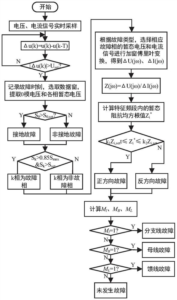
[0038] In the technical solutions disclosed in one or more embodiments, such as figure 1 As shown, the multi-terminal fault identification method of active distribution network based on transient signals includes the following steps:

[0039] Step 1. Obtain the transient voltage of the busbar at each measurement point and the three-phase current of each incoming and outgoing line of the busbar;

[0040] Step 2. For each measurement point, identify the fault phase and fault type according to the bus transient voltage;

[0041] Step 3. Calculate and judge the transient impedance based on the transient voltage and current signals of each measurement point, and obtain the fault direction of each measurement point;

[0042] Step 4. Fusing the fault direction of each measurement point to determine the fault section.

[0043] In this embodiment, the judgment of the transient signal by each measurement point is based on the fault direction of each measurement point, and the judgment...

Embodiment 2

[0149] The multi-terminal fault identification system for active distribution network based on transient signals provided in this embodiment includes: a protection device installed at each inlet and outlet of the busbar, and the protection device implements the transient state-based fault identification system described in Embodiment 1. The multi-terminal fault identification method of the active distribution network of the signal identifies the fault direction at the protection device, obtains the fault signal of the adjacent protection device, and compares the fault direction of the relevant measurement point to determine whether the section connected to the protection device has Fault.

Embodiment 3

[0151] This embodiment provides an active distribution network multi-terminal fault identification system based on transient signals, including:

[0152] Obtaining module: configured to obtain the transient voltage of the bus at each measurement point and the three-phase current of each incoming and outgoing line of the bus;

[0153] Fault phase and fault type judging module: configured to identify fault phase and fault type according to bus transient voltage for each measurement point;

[0154] Fault direction identification module: configured to calculate and judge the transient impedance based on the transient voltage and current signals of each measurement point, and obtain the fault direction of each measurement point;

[0155] Comparison identification module: configured to fuse the fault direction of each measurement point to determine the fault section.


PUM


Abstract

The invention provides an active power distribution network multi-terminal fault identification method and system based on transient signals. The method comprises the following steps: firstly, transient voltage being adopted to construct a protection starting criterion; comparing the integral average value of the zero-mode voltage in the protection time window with a zero-mode setting threshold value, judging whether a grounding fault occurs or not, comparing the integral average value of the transient voltage of each phase after the zero-mode component is filtered out in the protection time window with a set threshold value, and identifying a fault phase; then, according to the fault phase and the fault type, selecting a corresponding transient signal to perform windowed Fourier transform, extracting the voltage and current of a corresponding characteristic frequency band, calculating the transient impedance under the required characteristic frequency band, and judging the fault direction by comparing the root-mean-square value of the transient impedance with the protection setting impedance value; and finally, the fault position being judged through the multi-terminal fault direction information. The method disclosed by the invention is basically not influenced by factors such as transition resistance, DG permeability, network operation state and the like, has relatively lowrequirements on communication conditions, and can realize fault identification and comprehensive protection of the active power distribution network.

Description

technical field [0001] The present disclosure relates to the related technical field of active distribution network fault identification, and specifically relates to a transient signal-based multi-terminal fault identification method and system for an active distribution network. Background technique [0002] The statements in this section merely provide background information related to the present disclosure and may not necessarily constitute prior art. [0003] As more and more distributed generation (DG) are directly connected to the distribution network, the concept of active distribution network was proposed in the 2008 International Conference on Large Power Grids (CIGRE). Renewable energy, low line loss, flexible and reliable power supply and other advantages are considered to be the development direction of smart distribution network. However, the access of DG poses new challenges to distribution network relay protection. Since the traditional distribution network...

Claims


Application Information

Patent Timeline
Patent Type & Authority Applications(China)
IPC IPC(8): G01R31/08H02H7/22H02H7/26H02H7/28H02H1/00
CPCG01R31/086G01R31/085G01R31/088H02H7/22H02H7/26H02H7/28H02H1/0007
Inventor 孙良志郭学林邹贵彬贾玭王文东苑源任鹏飞蒋立潇郭久红洪亚李敬东
Owner 国网山东省电力公司聊城供电公司
Learn More