Automatic inspection equipment for power grid operation

A technology for automatic inspection and power grid operation. It is applied in the direction of using optical methods to test, measure electricity, and measure electrical variables. It can solve the problems of trouble finding hot spots, numerous equipment, and long time consumption, so as to avoid manual judgment errors, The effect of reducing carrying monitoring equipment and improving accuracy

Active Publication Date: 2020-11-17
广州市赛皓达智能科技有限公司
View PDF12 Cites 2 Cited by
  • Summary
  • Abstract
  • Description
  • Claims
  • Application Information

AI Technical Summary

Problems solved by technology

[0004]Currently, when the power grid staff is cruising in the on-site power grid operation, they need to carry visible light shooting equipment, infrared imaging shooting equipment and ultraviolet imaging shooting equipment one by one to carry out inspections for the above faults Monitoring, or installing visible light shooting equipment, infrared imaging shooting equipment and ultraviolet imaging shooting equipment one by one on the drone for high-altitude shooting, but this method needs to carry a lot of equipment, which needs to be disassembled and installed one by one. The time is long; because the image generated by the existing infrared imager is a color image, it is difficult for the power grid staff to correspond to the heating position of the power transmission equipment such as the pole tower according to the color image. False alarms occur; the ultraviolet image generated by a separate ultraviolet imager also has the problem of finding the ultraviolet signal and corresponding to the discharge position of the equipment.
[0005]On the other hand, most of the visible light images, infrared images and ultraviolet images captured by the above-mentioned shooting equipment are manually observed, analyzed and judged, and it is easy to appear due to human subjective assumptions. The monitoring error has the disadvantage of false alarm

Method used


Image

  • Automatic inspection equipment for power grid operation
  • Automatic inspection equipment for power grid operation
  • Automatic inspection equipment for power grid operation

Examples


Embodiment Construction

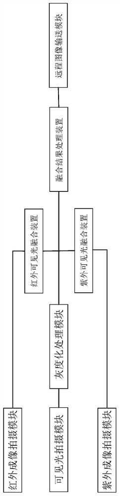
[0035] The following is attached Figure 1-7 The application is described in further detail.

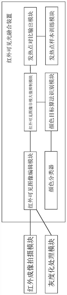
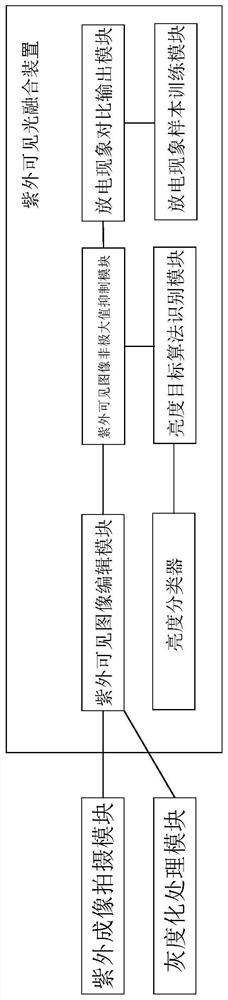
[0036] The embodiment of this application discloses an automatic inspection equipment for power grid operation, refer to Figure 1-3 , including a visible light shooting module for generating visible light images, an infrared imaging shooting module for generating infrared images, an ultraviolet imaging shooting module for generating ultraviolet images, and a gray scale for grayscale processing of generated visible light images processing module, infrared-visible light fusion device, ultraviolet-visible light fusion device and fusion result processing device, the visible light shooting module is connected with the gray scale processing module; Hot spot training sample module, infrared visible light image editing module for cropping and superimposing visible light images and infrared images, color classifier for setting color targets corresponding to hot spot temperatures, color targ...


PUM


Abstract

The invention relates to the technical field of power grid operation monitoring, in particular to automatic inspection equipment for power grid operation. The equipment comprises a visible light shooting module, an infrared imaging shooting module, an ultraviolet imaging shooting module, a graying processing module, an infrared visible light fusion device, an ultraviolet visible light fusion device and a fusion result processing device. The visible light, ultraviolet light and infrared light three-in-one fusion automatic inspection function can be realized, carrying of monitoring equipment isreduced, one-by-one disassembly and assembly are not needed, and time and labor are saved. A judgment result is output, the position of a heating point is accurately obtained, and fault misinformationis avoided. A heating point training sample is compared with an infrared visible light image through a convolutional neural network to improve the accuracy of finding the heating point, a discharge phenomenon training sample is compared with a discharge phenomenon visible light image through the convolutional neural network to improve the accuracy of finding a discharge phenomenon without manually observing the image for judgment, automatic and accurate cruise diagnosis is achieved, and the risk of manual judgment errors is avoided.

Description

technical field [0001] The present application relates to the technical field of power grid operation monitoring, in particular to an automatic inspection device for power grid operation. Background technique [0002] With the continuous expansion of the grid scale of the power system and the continuous improvement of power load requirements, the damage and failure of various types of high-voltage equipment used in the power system are also increasing, and the corresponding requirements for preventive maintenance are also increasing. Equipment such as transmission poles and towers work in an atmospheric environment. In some cases, with the reduction of insulation performance, structural defects, local heating or surface partial discharge phenomena appear. [0003] Conventional monitoring methods can use photography or photography to check and judge whether there are structural defects visible to the naked eye; local heating is difficult to observe directly, and infrared imag...

Claims


Application Information

Patent Timeline
Patent Type & Authority Applications(China)
IPC IPC(8): G01R31/12G01R31/08G06N3/04G06N3/08
CPCG01R31/1218G01R31/086G01R31/088G06N3/08G06N3/045
Inventor 刘鑫文锋秦哲马徐行林月奎
Owner 广州市赛皓达智能科技有限公司
Why Eureka
Try Eureka