Six-suspension-pole internal and external double-rotor type magnetic suspension slice switch reluctance motor

A dual-rotor, thin-film switch technology, applied in AC motor control, magnetic circuit, electric components, etc., can solve the problems of reducing suspension force density and torque density, torque tooth occupancy, large radial space, etc. The effect of torque and suspension force, low cost and power consumption, and simple control

Pending Publication Date: 2020-11-17
HUAIYIN INSTITUTE OF TECHNOLOGY
View PDF1 Cites 3 Cited by
  • Summary
  • Abstract
  • Description
  • Claims
  • Application Information

AI Technical Summary

Problems solved by technology

[0003] The technical characteristics of the existing magnetic levitation switched reluctance motors are concentrated in two aspects. 1. Both are single rotor and single stator structures, which limit the extension of their application fields; 2. Magnetic levitation switched reluctance motors are often wound on the stator teeth at the same time. Torque winding and levitation winding, both of which are energized at the same time, work together to generate levitation force and torque, there is strong coupling between the two, the control is complicated, and it is difficult to achieve high-speed and high-precision control. A permanent magnet bias bearingless switch is patented in China Application number of reluctance motor: CN102306995B, using magnetic isolation material to separate the suspension teeth and torque teeth from each other, realizing the independent control of suspension force and torque, but the number of suspension teeth in this structure is 4, and the torque core is double rotor teeth structure, two bipolar switching power amplifiers or four unipolar switching power amplifiers are required to achieve two-degree-of-freedom suspension, and the torque teeth of this structure occupy a larger radial space, resulting in serious suspension tooth area and rotor tooth area Restricted, reducing suspension force density and torque density

Method used


Image

  • Six-suspension-pole internal and external double-rotor type magnetic suspension slice switch reluctance motor
  • Six-suspension-pole internal and external double-rotor type magnetic suspension slice switch reluctance motor
  • Six-suspension-pole internal and external double-rotor type magnetic suspension slice switch reluctance motor

Examples


Embodiment Construction

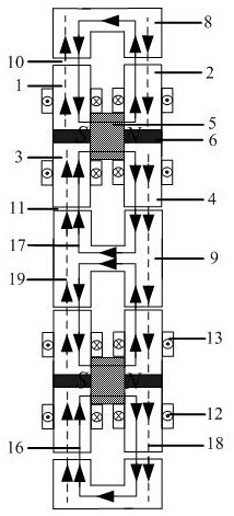
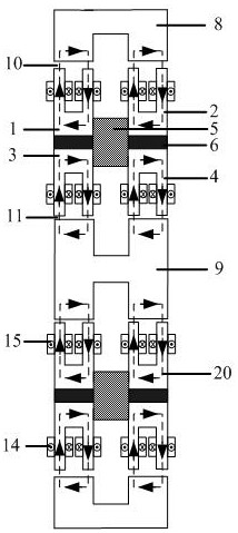
[0022] The present invention will be further described below in conjunction with the accompanying drawings. The following examples are only used to illustrate the technical solution of the present invention more clearly, but not to limit the protection scope of the present invention.

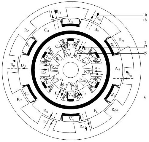
[0023] Specific implementation methods such as Figure 1-4 As shown, a magnetic levitation switched reluctance motor with six levitation poles and inner and outer double rotors includes a stator, an inner rotor, an outer rotor, and a rotating shaft. The stator includes a left motor stator core, a right motor stator core, a permanent magnet ring 5 and two magnetic isolation aluminum rings 6 . The left motor stator core and the right motor stator core are respectively divided into left outer motor stator core 1, left inner motor stator core 3, right outer motor stator core 2, right inner motor stator core 4 by their corresponding magnetic isolation aluminum rings 6, left The outer circumference ...


PUM


Abstract

The invention relates to the field of reluctance motors, and discloses a magnetic levitation switched reluctance motor which comprises a stator, an inner rotor and an outer rotor. The stator comprisesa motor stator core, a permanent magnet ring and a magnetism isolating aluminum ring; the motor stator iron core is divided into an outer side motor stator iron core and an inner side motor stator iron core by the magnetism isolating aluminum ring, six outer side suspension teeth and torque teeth and six inner side suspension teeth and torque teeth are evenly distributed on the surface of the outer side motor stator iron core and the surface of the inner side motor stator iron core respectively, and the inner side torque teeth and the outer side torque teeth are connected with the motor stator iron core through magnetism isolating blocks. Windings are wound on the suspension teeth and the torque teeth; the permanent magnet ring is connected with left and right motor stator cores; rotor teeth are uniformly distributed on the inner side of the outer side rotor iron core and the outer side of the inner side rotor iron core respectively, and an outer side air gap and an inner side air gapare formed between the rotor teeth and the outer and inner side motor stator iron cores respectively; according to the reluctance motor, stable suspension of the inner rotor and the outer rotor can be achieved only through two three-phase inverters, suspension control and torque control are not coupled, and the reluctance motor has the advantages of being compact in structure, low in manufacturing cost and easy to control.

Description

technical field [0001] The invention relates to the field of magnetic levitation switched reluctance motors, in particular to a magnetic levitation flake switched reluctance motor with six levitation poles and inner and outer double rotors. Background technique [0002] There are no permanent magnets and windings on the rotor of the magnetic levitation switched reluctance motor. It has the advantages of no friction and wear, simple structure, firmness, and high strength. It is easy to achieve high-speed operation and has great application prospects in high-speed applications. [0003] The technical characteristics of the existing magnetic levitation switched reluctance motors are concentrated in two aspects. 1. Both are single rotor and single stator structures, which limit the extension of their application fields; 2. Magnetic levitation switched reluctance motors are often wound on the stator teeth at the same time. Torque winding and levitation winding, both of which are ...

Claims


Application Information

Patent Timeline
Patent Type & Authority Applications(China)
IPC IPC(8): H02K16/02H02K1/24H02K1/12H02K1/17H02N15/00H02P25/092
CPCH02K1/12H02K1/17H02K1/246H02K16/02H02K2201/03H02K2213/03H02N15/00H02P25/092
Inventor 李洪海王紫欣张涛叶小婷武莎莎丁祖军刘斌丁卫红
Owner HUAIYIN INSTITUTE OF TECHNOLOGY
Why Eureka
Try Eureka