
Stamping head lubricating mechanism

A technology of lubricating mechanism and punching head, applied in the field of punching die, can solve the problems of burr of punching products, affecting the quality of punching, damage of punching head, etc., so as to reduce friction and improve production quality.

Active Publication Date: 2020-11-20
浙江艾信汽车零部件股份有限公司
View PDF10 Cites 7 Cited by
  • Summary
  • Abstract
  • Description
  • Claims
  • Application Information

AI Technical Summary

Problems solved by technology

[0003] In the stamping die, the component that can exert stamping force on the plate, strip, pipe and profile is called the stamping head. When the stamping head stamps circular parts, the stamping head is generally directly in contact with the material for stamping, but When the stamping head is stamped for a long time, it will produce a large friction force with the material, which will cause damage to the stamping head, causing burrs to appear on the stamped finished product, and some materials that have been placed for a long time will be stamped on the material. There may be dust and impurities attached. If it is not cleaned, it will seriously affect the quality of punching and even damage the punching head

Method used


Image

  • Stamping head lubricating mechanism
  • Stamping head lubricating mechanism
  • Stamping head lubricating mechanism

Examples


Embodiment Construction

[0027] In order to make the technical means, creative features, goals and effects achieved by the present invention easy to understand, the present invention will be further described below in conjunction with specific embodiments.

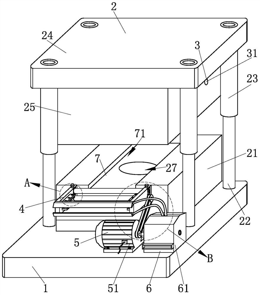
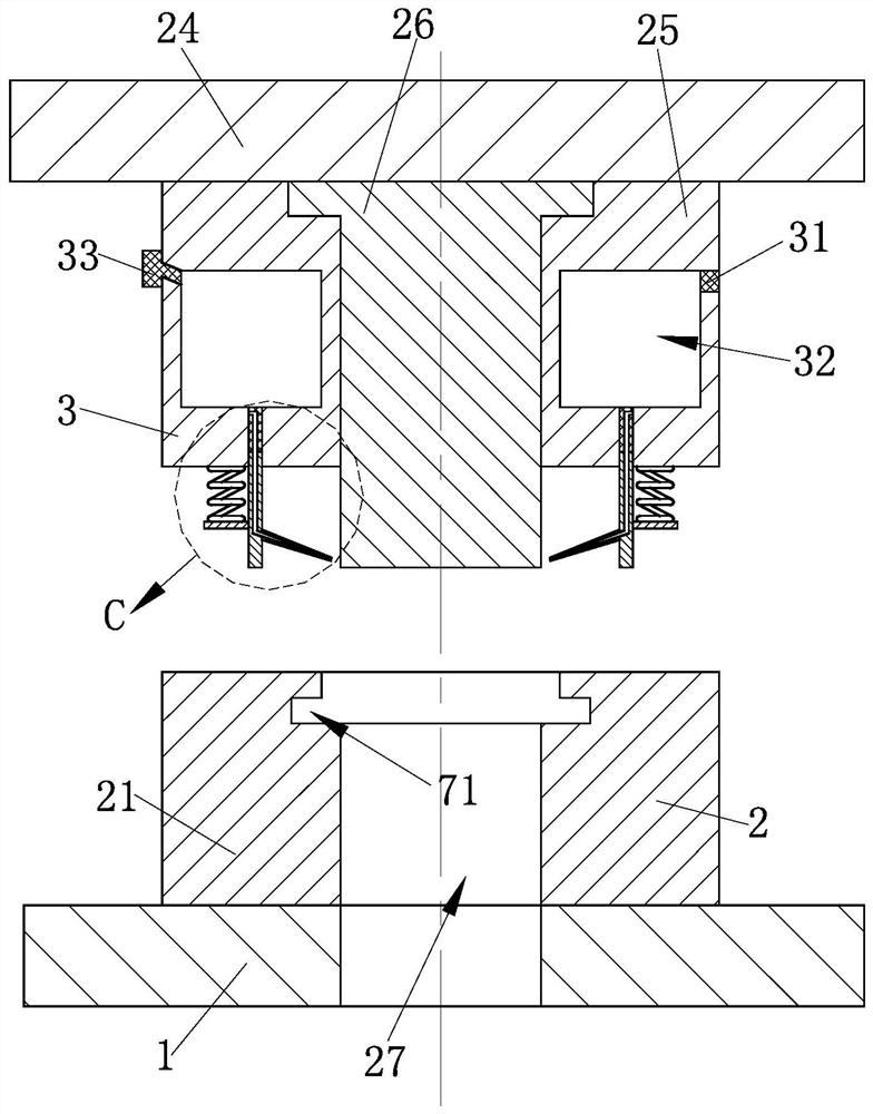
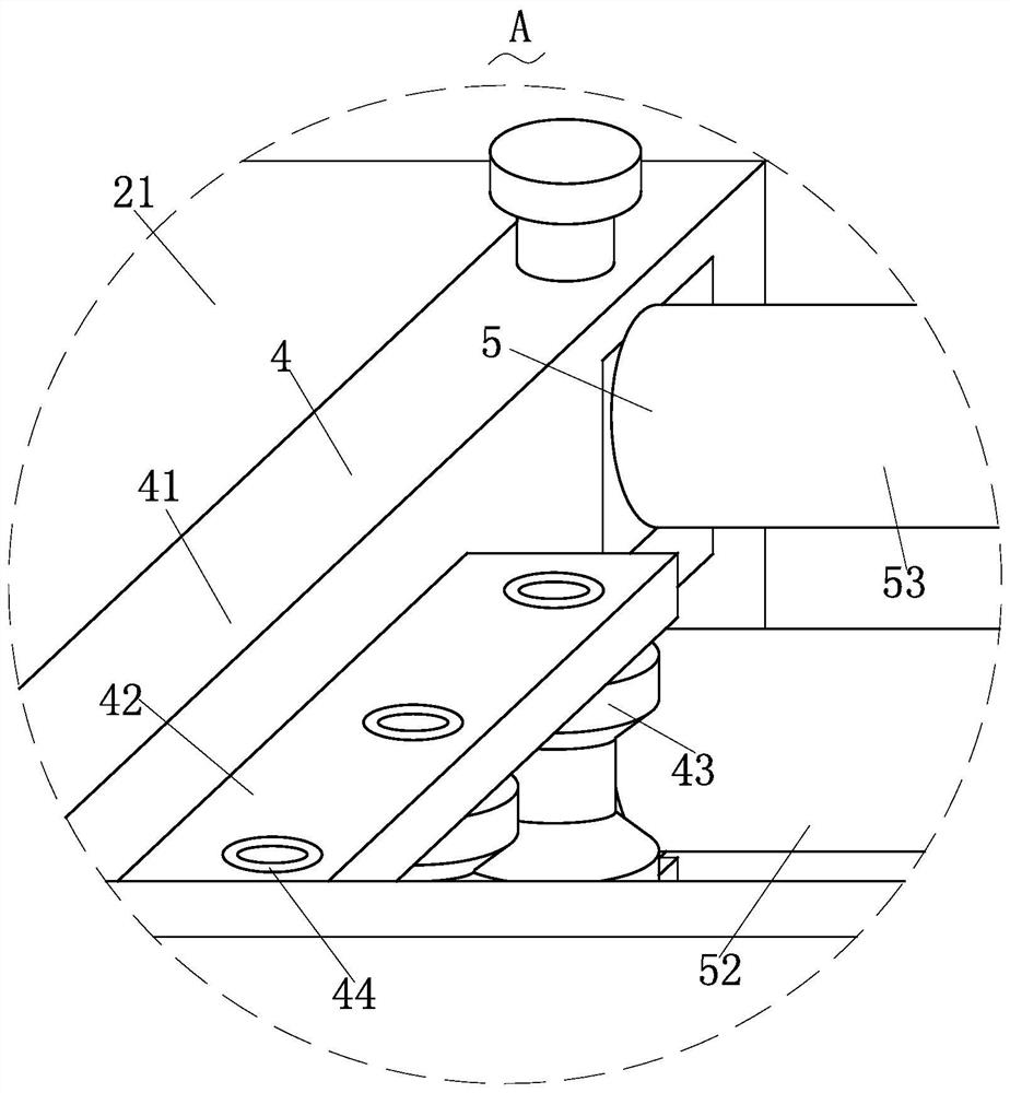
[0028] Such as Figure 1-Figure 8 As shown, a lubricating mechanism for a stamping head according to the present invention includes a base 1, a stamping structure 2, a lubricating structure 3, a guiding structure 4, a feeding structure 5, a cleaning structure 6 and a pressing structure 7, which are used to connect and fix and The top of the base 1 where other parts are installed is provided with the stamping structure 2 for stamping circular parts, and the stamping structure 2 is provided inside the stamping structure 2 for oiling and lubricating the stamping structure 2. Described lubricating structure 3; The described guiding structure 4 that is used for guiding metal sheet stock is installed at one end of described stamping structure 2, is inst...


PUM


Abstract

The invention relates to the field of stamping dies, in particular to a stamping head lubricating mechanism. The stamping head lubricating mechanism comprises a base, a stamping structure, a lubricating structure, a guide structure, a feeding structure, a cleaning structure and a pressing structure. Through the arrangement of the stamping structure, long sheet materials can be stamped into required round parts one by one, the lubricating structure can be synchronously driven to work while the stamping structure carries out stamping work, and through work of the lubricating structure, oil injection lubrication work can be automatically carried out on assemblies in the stamping structure during stamping, so that the friction force between the stamping assembly and the sheet materials can bereduced, the situation that burrs appear on the periphery of a stamped finished product part can be avoided, and thus the effect of greatly improving the production quality is achieved; and the cleaning structure can be synchronously driven to work while the feeding structure works, dust and chippings on the metal sheet materials to be punched can be blown off, and therefore the dust and the impurities can be prevented from being punched along with the metal sheet materials.

Description

technical field [0001] The invention relates to the field of stamping dies, in particular to a lubricating mechanism for a stamping head. Background technique [0002] Stamping is a forming processing method that applies external force to plates, strips, pipes and profiles by presses and molds to cause plastic deformation or separation to obtain workpieces (stamping parts) of required shape and size. Stamping and forging belong to plastic processing (or pressure processing) and are collectively called forging. The blanks for stamping are mainly hot-rolled and cold-rolled steel sheets and strips. Stamping die is a special process equipment for processing materials (metal or non-metal) into parts (or semi-finished products) in cold stamping processing, called cold stamping die (commonly known as cold stamping die). Stamping is a pressure processing method that uses a mold installed on a press to apply pressure to the material at room temperature to cause separation or plasti...

Claims


Application Information

Patent Timeline
Patent Type & Authority Applications(China)
IPC IPC(8): B21D28/06B21D28/04B21D28/14B21D37/18B21D43/02B21D43/09B21D1/02B08B5/02
CPCB21D28/06B21D28/04B21D28/14B21D37/18B21D43/023B21D43/09B21D1/02B08B5/023
Inventor 杨永建
Owner 浙江艾信汽车零部件股份有限公司
Learn More