A cement column pouring equipment for fruit racks

A technology for cement columns and fruit racks, applied in ceramic molding machines, manufacturing tools, supply devices, etc., can solve the problems of low labor intensity, high labor intensity, and low cement column pouring efficiency, so as to improve efficiency and reduce labor intensity. Effect

Active Publication Date: 2021-11-26
何永捌
View PDF5 Cites 0 Cited by
  • Summary
  • Abstract
  • Description
  • Claims
  • Application Information

AI Technical Summary

Problems solved by technology

[0005] In order to overcome the disadvantages that people need to add cement and steel bars many times to pour the cement column, and also need to squeeze the cement to make the cement column smooth and firm, the labor intensity of such frequent operations is relatively high, and the pouring efficiency of the cement column is low. , the technical problem to be solved by the present invention is to provide a cement column pouring equipment for fruit racks with relatively low labor intensity and high efficiency of cement column pouring

Method used


Image

  • A cement column pouring equipment for fruit racks
  • A cement column pouring equipment for fruit racks
  • A cement column pouring equipment for fruit racks

Examples


Embodiment 1

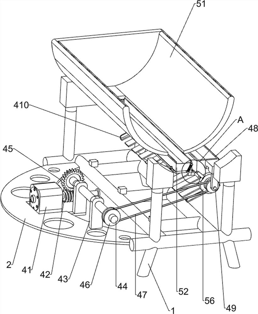
[0023] A kind of cement column pouring equipment for fruit racks, such as Figure 1-3 As shown, it includes a platform 1, a mounting plate 2, a mold box 3, a blanking mechanism 4 and a material leakage mechanism 5, the left side of the platform 1 is connected with a mounting plate 2, and the middle part of the platform 1 is placed with a mold box 3, A blanking mechanism 4 is connected between the platform 1 and the mounting plate 2 , and a material leakage mechanism 5 is connected between the platform 1 and the blanking mechanism 4 .

[0024] Blanking mechanism 4 comprises reduction motor 41, worm screw 42, bearing 43, rotating rod 44, worm wheel 45, belt pulley 46, flat belt 47, placement box 48, feeding rod 49 and baffle plate 410, the middle of mounting plate 2 tops A reduction motor 41 is installed at the position, and the middle part of the output shaft of the reduction motor 41 is connected with a worm screw 42. The front side of the mounting plate 2 top is connected wit...

Embodiment 2

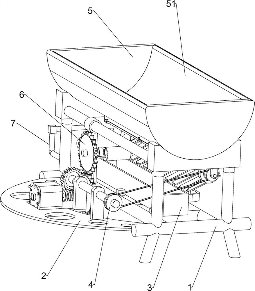
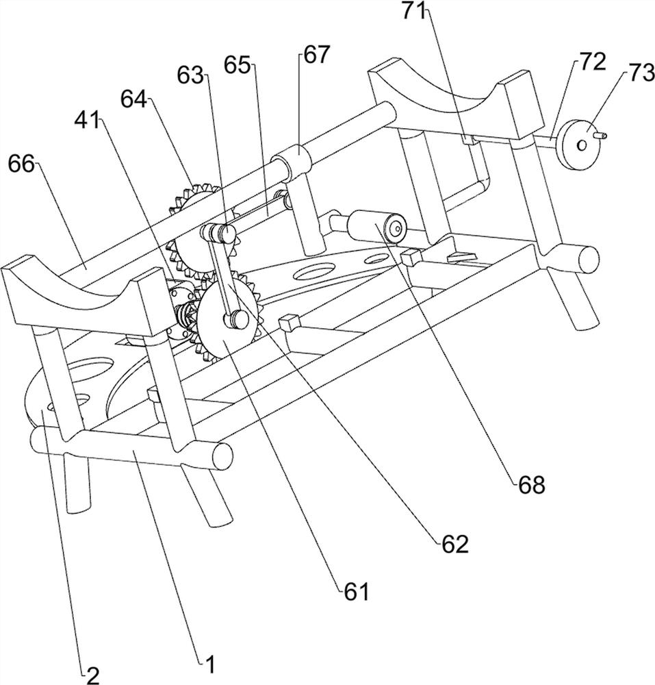
[0028] On the basis of Example 1, such as Figure 4 Shown, also include extruding mechanism 6, extruding mechanism 6 includes first gear 61, first connecting rod 62, rotating shaft 63, second gear 64, second connecting rod 65, slide bar 66, sliding sleeve 67 and The drum 68 is connected with the first gear 61 and the first connecting rod 62 at the tail end of the output shaft of the reduction motor 41, the first connecting rod 62 is connected with the right side of the first gear 61, and the top of the first connecting rod 62 is rotationally connected with Rotating shaft 63, the left side of rotating shaft 63 is connected with the second gear 64, and the second gear 64 and the first gear 61 mesh with each other, and the right side of rotating shaft 63 is connected with the second connecting rod 65 rotationally, and the rear end of the second connecting rod 65 Rotationally connected with sliding sleeve 67, the rear side of sliding sleeve 67 bottom is connected with cylinder 68,...

Embodiment 3

[0031] On the basis of Example 2, such as Figure 4 Shown, also include fixed mechanism 7, fixed mechanism 7 includes L-shaped fixed rod 71, round rod 72 and rotating disk 73, the left rear side of stand 1 is connected with L-shaped fixed rod 71, the top of L-shaped fixed rod 71 A round rod 72 is connected, and the right side of the round rod 72 is connected with a turntable 73 in a threaded manner.

[0032]When people need to pour the cement column, turn the turntable 73 and take it out, put the whole roll of film into the round rod 72, then turn the turntable 73 to reset, people only need to pull one end of the film to cover the film on the mold box 3 In this way, the film covering on the mold box 3 can be quickly realized, and the film is covered on the mold box 3 without the cooperation of two people, which further improves the efficiency of people pouring the cement column.


PUM


Abstract

The invention relates to a cement column pouring equipment, in particular to a cement column pouring equipment for fruit racks. The technical problem to be solved by the present invention is to provide a cement pillar pouring equipment for fruit stands with relatively low labor intensity and high cement pillar pouring efficiency. In order to solve the above-mentioned technical problems, the present invention provides such a cement column pouring equipment for fruit racks, which includes: a stand, which is connected to the mounting plate; a mold box, which is placed on the stand; a feeding mechanism, which is connected to the stand Between the rack and the mounting plate; the material leakage mechanism is connected between the stand and the unloading mechanism. The present invention achieves the rapid realization of pouring the cement column through the feeding mechanism and the material leakage mechanism, without the need for people to add cement and steel bars multiple times to pour the cement column.

Description

technical field [0001] The invention relates to a cement column pouring equipment, in particular to a cement column pouring equipment for fruit racks. Background technique [0002] Recently, due to the country's vigorous promotion of entrepreneurship, many people have planted grapes, dragon fruit, kiwi, passion fruit and other fruits in large quantities according to local conditions. These fruits need to be erected on pillars so that the vines of the fruits can grow along the pillars. At present, wooden frames and iron frames are generally used to build fruit frames. Although the cost of wooden frames is low, they are easy to decay and damage, are not firm, and have a short service life. high. However, the use cost of cement columns is lower, stronger, less prone to decay and rust, and can be used on fruit racks. [0003] At present, for the pouring of cement columns, most people frequently add cement and steel bars to pour the cement columns by hand. It is also necessary ...

Claims


Application Information

Patent Timeline
Patent Type & Authority Patents(China)
IPC IPC(8): B28B13/02B28B7/38
CPCB28B7/382B28B13/0215B28B13/0295
Inventor 耿雪林何永捌
Owner 何永捌
Why Eureka
Try Eureka