Teeth synergistic three-dimensional wobble plate piston engine

A piston engine, three-dimensional technology, applied in the direction of engine components, machines/engines, mechanical equipment, etc., can solve the problems of axial piston structure failure, machine failure, complex structure, etc., and achieve unfavorable load reduction, high power-to-weight ratio, windward small area effect

Active Publication Date: 2022-05-24
重庆交通大学绿色航空技术研究院 +1
View PDF0 Cites 0 Cited by
  • Summary
  • Abstract
  • Description
  • Claims
  • Application Information

AI Technical Summary

Problems solved by technology

[0003] From the above structure, it can be seen that relative to the cylinder body, it is expected that there will be no relative rotation in the circumferential direction between the wobble plate and the cylinder body. The piston still transmits the power of the piston to the wobble plate, and the wobble plate is subject to the component force in the circumferential direction. Therefore, the connecting rod also constrains the coordinated action between the wobble plate and the cylinder (piston), so the bearing is more complicated and has various directions. The deflection moment; therefore, the usual structure adopts the sliding shoe structure to adapt to the azimuth change in all directions and undertake more complex deflection moment, the structure is more complicated; the sliding shoe structure needs to have sufficient lubrication, which not only makes the structure extremely complicated, but also prone to occurrence Wear leads to machine failure; due to the above problems, the existing technology is rarely used in the case of engines, high speed and load will quickly fail the axial piston structure

Method used


Image

  • Teeth synergistic three-dimensional wobble plate piston engine
  • Teeth synergistic three-dimensional wobble plate piston engine
  • Teeth synergistic three-dimensional wobble plate piston engine

Examples


Embodiment Construction

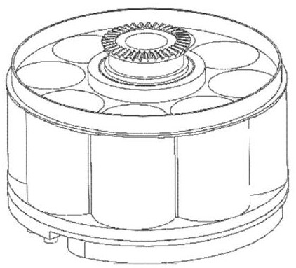
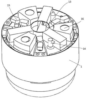
[0040] As shown in the figure, the teeth cooperative three-dimensional wobble plate piston engine of the present invention includes a base body 1, a main shaft 7, a cylinder body 2, a transmission assembly and a cooperative tooth assembly;

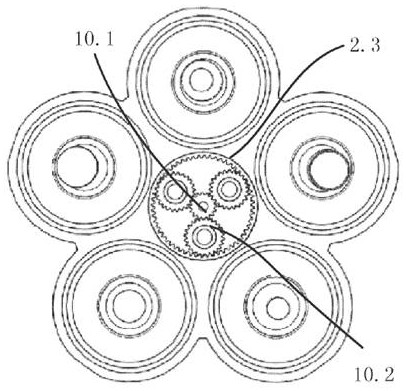
[0041] The cylinder block 2 has a central axis, and the cylinder block includes at least two cylinders arranged in a circular array parallel to the central axis, as shown in the figure, the axes of the cylinders are parallel to the central axis; a piston 9 is arranged in cooperation with the cylinders , a connecting rod 8 is arranged in cooperation with the piston 9, and the cylinder body 2 is fixedly arranged. The fixed arrangement here refers to the overall fixing of the cylinder body during use, which can be fixed on the basis of setting, and will not be repeated here; As shown in the figure, the cylinder body is fixed on a base body, and the setting method can be realized by using a common mechanical structure, so I won’t repeat it here...


PUM


Abstract

The invention discloses a tooth-cooperated three-dimensional wobble plate piston engine, which includes a base body, a main shaft, a cylinder body, a transmission assembly and a cooperating tooth assembly; the cylinder body includes at least two cylinders arranged in a circular array in parallel around the central axis, and the transmission assembly includes a wobble plate , the cooperative tooth assembly includes a first bevel gear fixed on the wobble plate and a second bevel gear fixed on the cylinder body, the first bevel gear and the second bevel gear form meshing, so that the wobble plate and the cylinder Synergy is formed between the cylinders in the circumferential direction, so as to coordinate the synchronization between the cylinder and the swing plate in the circumferential direction, so that the connecting rod only transmits the reciprocating driving force, and does not participate in the transmission of the synchronization of the swing plate and the cylinder in the circumferential direction. load, remove the commonly used sliding shoe structure in the prior art, simplify the connection relationship between the connecting rod and the piston, and the connecting rod and the swing plate, so that the overall structure is simple and light, prolong the service life of the connecting pair, and save manufacturing and use costs. The invention adopts the rotary cylinder gas distribution structure, which is compact, simple, high power-to-weight ratio, large power-to-volume ratio, small radial load of the piston, and high mechanical efficiency of the whole machine; Small resistance, suitable for aero-engines.

Description

technical field [0001] The invention relates to the field of transmission drive, in particular to a three-dimensional wobble plate piston engine coordinated by teeth. Background technique [0002] The axial piston device is driven or driven by a cylinder arranged around a central axis, a piston matched with the cylinder, and a rotating wobble plate; the basic structure is that the piston is connected to the wobble plate through a connecting rod, and the reciprocating motion of the piston is transmitted to the oscillating plate through the connecting rod. The disk is transformed into a rotational output by using the cam transmission principle of the wobble disk; or, the wobble disk is driven by the periodic axial swing to periodically change the axial position and drive the piston through the connecting rod to form a reciprocating motion and perform work. [0003] From the above structure, it can be seen that relative to the cylinder body, it is expected that there will be no...

Claims


Application Information

Patent Timeline
Patent Type & Authority Patents(China)
IPC IPC(8): F02B75/32F02B77/00
CPCF02B75/32F02B77/00
Inventor 周留成延黎柳平聂祥樊邓涛黄中桓苗卓广刘东亮林敏李瑞柳明张雨潇
Owner 重庆交通大学绿色航空技术研究院
Why Eureka
Try Eureka