Gas-liquid separation device and method, crude oil extraction system and crude oil detection system

A gas-liquid separation device, crude oil technology, applied in the direction of measuring devices, material separation, analysis of materials, etc., can solve the problems of liquid light hydrocarbon retention, poor separation effect, measurement error, etc., to achieve the effect of gas-liquid separation

Pending Publication Date: 2020-11-20
CHINA PETROLEUM & CHEM CORP +1
View PDF9 Cites 0 Cited by
  • Summary
  • Abstract
  • Description
  • Claims
  • Application Information

AI Technical Summary

Problems solved by technology

Due to the narrow space of the Erlenmeyer flask and the condition of normal pressure, the separation effect is poor, and a large amount of liquid light hydrocarbons are retained after the fluid cools down, resulting in large errors in the measurement of the gas-oil ratio of the fluid and some related physical parameters.

Method used


Image

  • Gas-liquid separation device and method, crude oil extraction system and crude oil detection system
  • Gas-liquid separation device and method, crude oil extraction system and crude oil detection system
  • Gas-liquid separation device and method, crude oil extraction system and crude oil detection system

Examples


Embodiment 1

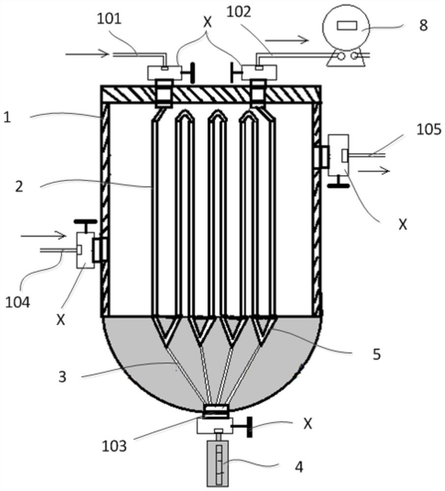
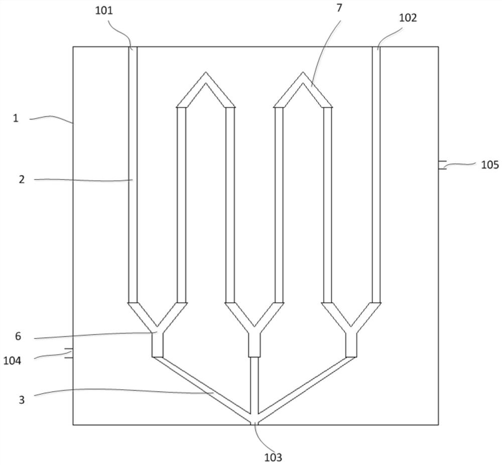
[0068] This embodiment provides a gas-liquid separation device for fluid obtained by extracting light hydrocarbons from crude oil with high-pressure gas. See figure 2 , the gas-liquid separation device comprises: a housing 1, 8 fluid inlet pipelines 2, 4 liquid drainage pipelines 3, and a liquid collector 4; the housing 1 has a fluid inlet 101, a gas outlet 102, a liquid outlet 103, a condensation The medium inlet 104, the condensing medium outlet 105, and the base 106; the fluid inlet 101, the gas outlet 102, the liquid outlet 103, the condensing medium inlet 104, and the condensing medium outlet 105 are all provided with a valve X; the base 106 is a hemispherical solid structure, and the base 106 is provided with 4 V-shaped grooves 5, each V-shaped groove has two through holes, and 8 through holes are located on the upper surface of the base 106; each fluid inlet line is connected to one of the through holes , and the two through-holes of each V-groove are respectively in ...

Embodiment 2

[0070] This embodiment provides a crude oil extraction system. The crude oil extraction system includes: a crude oil extraction device and the above-mentioned gas-liquid separation device; the crude oil extraction device communicates with the fluid inlet of the gas-liquid separation device.

Embodiment 3

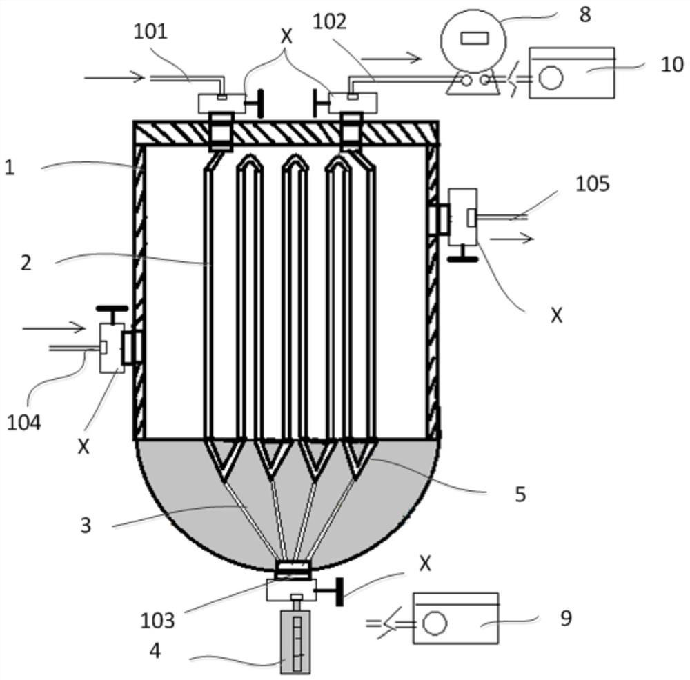
[0072] This embodiment provides a crude oil detection system. See image 3 , the crude oil detection system comprises: the above-mentioned gas-liquid separation device, a liquid chromatography system 9, and a gas chromatography system 10, the liquid chromatography system 9 is used to detect the liquid in the liquid collector 4, the gas chromatography system 10 and the gas meter 8 connected.


PUM

PropertyMeasurementUnit
lengthaaaaaaaaaa

Abstract

The invention belongs to the technical field of petrochemical equipment, and relates to a gas-liquid separation device for fluid obtained by extracting crude oil light dydrocarbon through high-pressure gas, which comprises a shell, at least two fluid introduction pipelines, a liquid drainage pipeline and a liquid collector. The shell is provided with a fluid inlet, a gas outlet, a liquid outlet, acondensing medium inlet and a condensing medium outlet. The at least two fluid introduction pipelines and the liquid drainage pipeline are positioned in the shell. All the fluid introduction pipelines are communicated in sequence, the included angle between each fluid introduction pipeline and the horizontal plane is greater than 0 degree and less than or equal to 90 degrees, the lower end of each fluid introduction pipeline is communicated with the upper end of the liquid drainage pipeline, the upper end of a first fluid introduction pipeline in the at least two fluid introduction pipelinesis communicated with the fluid inlet, and the upper end of a last fluid introduction pipeline is communicated with the gas outlet. The lower end of the liquid drainage pipeline, the liquid outlet andthe liquid collector are sequentially communicated. The gas-liquid separation device can quickly realize gas-liquid separation under the condition of high pressure.

Description

technical field [0001] The invention belongs to the technical field of petrochemical equipment, and more specifically relates to a gas-liquid separation device, a gas-liquid separation method, a crude oil extraction system, and a crude oil detection system for fluid obtained by extracting light hydrocarbons from crude oil with high-pressure gas. Background technique [0002] The high-temperature and high-pressure physical properties (PVT) parameters of crude oil are widely used. They are indispensable data for reservoir simulation and reservoir engineering calculations, and are the basis for studying reservoir driving types, calculating reservoir reserves, and determining oilfield development methods. [0003] The practice of oil and gas field development and production shows that, in addition to pure gas reservoirs, the development, production and surface technology of condensate gas reservoirs and oil reservoirs will experience fluid phase states such as mutual dissolution ...

Claims


Application Information

Patent Timeline
Patent Type & Authority Applications(China)
IPC IPC(8): G01N30/02G01N30/06
CPCG01N30/02G01N30/06G01N2030/062
Inventor 王锐赵淑霞吕成远伦增珉崔茂蕾胡伟王欣杨阳肖朴夫唐永强
Owner CHINA PETROLEUM & CHEM CORP
Why Eureka
Try Eureka