Low-temperature-drift relative plane mounting differential integrated resonant accelerometer
A surface mount, accelerometer technology, applied in the direction of measurement of acceleration, speed/acceleration/shock measurement, measurement device, etc., can solve the problem of inability to completely eliminate errors, reduce the basic accuracy of accelerometers, and difficult to implement the pressure-bonded gold wire micro-assembly process Increase and other problems to achieve the effect of reducing thermal stress, reducing difficulty, and small residual stress in processing
- Summary
- Abstract
- Description
- Claims
- Application Information
AI Technical Summary
Problems solved by technology
Method used
Image

Examples
Embodiment Construction
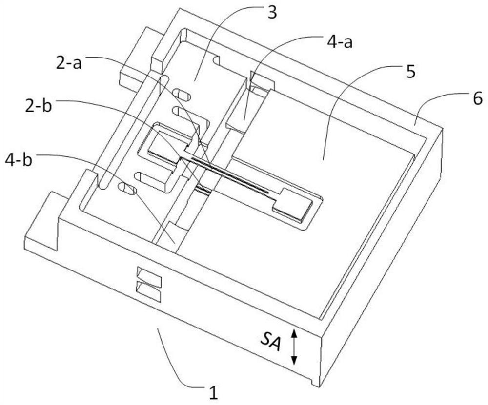
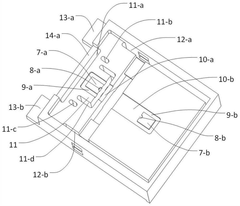
[0026] The structure and working principle of the present invention will be described in detail below in conjunction with the accompanying drawings.
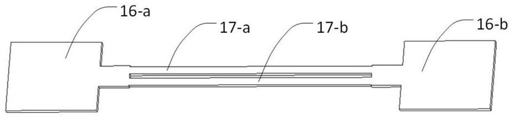
[0027] refer to figure 1 , a low-temperature drift relative plane mount differential type integrated resonant accelerometer, including a metal base 1 and a first double-end fixed support quartz tuning fork 2-a, a second double-end fixed support quartz tuning fork 2-b, and a metal base 1 Including a metal base 3, a first flexible hinge 4-a, a second flexible hinge 4-b, a mass block 5 and a metal frame 6, the mass block 5 passes through the first flexible hinge 4-a, the second flexible The hinge 4-b is connected to the metal base 3, and the left and right sides and the front side of the metal base 3 are connected to the metal frame 6; the first double-end fixed support quartz tuning fork 2-a and the second double-end fixed support quartz tuning fork 2 -b has the same structure, mounted on the front and back of the metal substrate...
PUM
 Abstract
Description
Claims
Application Information
 - Generate Ideas
- Intellectual Property
- Life Sciences
- Materials
- Tech Scout
- Unparalleled Data Quality
- Higher Quality Content
- 60% Fewer Hallucinations
Browse by: Latest US Patents, China's latest patents, Technical Efficacy Thesaurus, Application Domain, Technology Topic, Popular Technical Reports.
© 2025 PatSnap. All rights reserved.Legal|Privacy policy|Modern Slavery Act Transparency Statement|Sitemap|About US| Contact US: help@patsnap.com