Spatial light phase modulator

A technology of phase modulator and spatial light, which is applied in the directions of instruments, optics, nonlinear optics, etc., can solve the problems of low anti-damage threshold, small linear response range, and difficulty in flexible application, and achieve high anti-damage threshold and linear response range wide, low insertion loss effect

Pending Publication Date: 2020-11-20
NAT UNIV OF DEFENSE TECH
View PDF0 Cites 0 Cited by
  • Summary
  • Abstract
  • Description
  • Claims
  • Application Information

AI Technical Summary

Problems solved by technology

[0007] In order to overcome the defects of the existing phase modulators such as low anti-damage threshold, small linear response range, and difficulty in being flexibly applied to the spatial optical path, the present invention proposes a spatial optical phase modulator

Method used


Image

  • Spatial light phase modulator
  • Spatial light phase modulator
  • Spatial light phase modulator

Examples


Embodiment 1

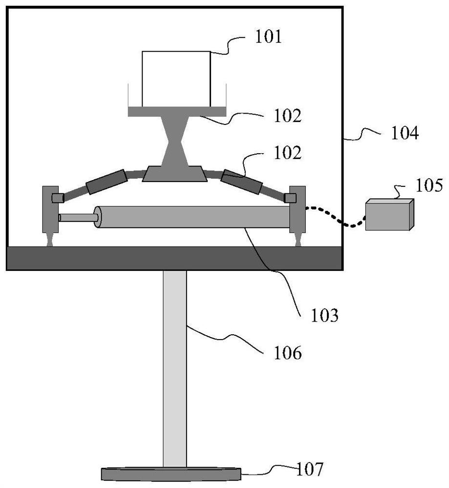
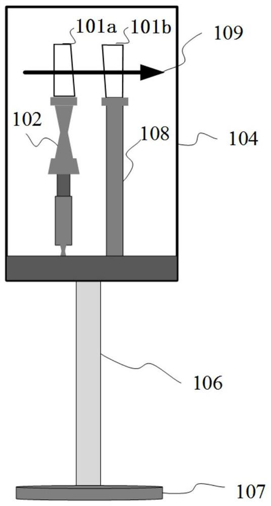
[0028] see figure 1 with figure 2 , this embodiment provides a spatial optical phase modulator, which is a piezoelectric ceramic-driven spatial optical phase modulator based on a flexible hinge structure, including a double wedge mirror 101, a flexible hinge structure 102, a piezoelectric ceramic 103, Encapsulation case 104 , piezoelectric ceramic controller 105 , case support rod 106 , support base 107 , and second support structure 108 . The double wedge mirror 101 is composed of a first wedge mirror 101a and a second wedge mirror 101b.

[0029] The first wedge mirror 101a and the second wedge mirror 101b are vertically supported by the first support structure and the second support structure 108 respectively, and the wedge surfaces of the first wedge mirror 101a and the second wedge mirror 101b are vertically symmetrically arranged. Both the first wedge mirror 101a and the second wedge mirror 101b are high lenses with a transmittance greater than or equal to 99%, and are...

Embodiment 2

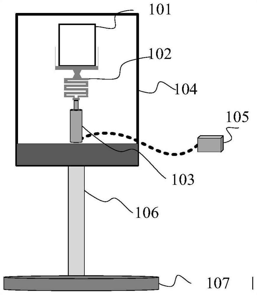
[0037] see image 3 with Figure 4 , this embodiment provides a spatial optical phase modulator, which is a piezoelectric ceramic-driven spatial optical phase modulator based on a flexible hinge structure, including a double wedge mirror 101, a flexible hinge structure 102, a piezoelectric ceramic 103, Encapsulation case 104 , piezoelectric ceramic controller 105 , case support rod 106 , support base 107 , and second support structure 108 . The double wedge mirror 101 is composed of a first wedge mirror 101a and a second wedge mirror 101b.

[0038] The difference from Embodiment 1 is that the piezoelectric ceramics 103 in this embodiment are arranged vertically. The flexible hinge structure is a linear or S-shaped flexible support arranged in the vertical direction, and the first wedge mirror 101a is arranged on the upper end surface of the flexible support.

[0039] The piezoelectric ceramic controller 105 controls the piezoelectric ceramic 103 to produce a small displacem...


PUM

PropertyMeasurementUnit
reflectanceaaaaaaaaaa
transmittivityaaaaaaaaaa

Abstract

In order to overcome defects that an existing phase modulator is low in anti-damage threshold value, small in linear response interval, difficult to be flexibly applied to a spatial light path and thelike, the invention provides a spatial light phase modulator comprising a double-wedge-shaped mirror that is composed of a first wedge-shaped mirror and a second wedge-shaped mirror. Wedge-shaped surfaces of the first wedge-shaped mirror and the second wedge-shaped mirror are vertically and oppositely arranged; the first wedge-shaped mirror and the second wedge-shaped mirror are vertically supported by a first supporting structure and a second supporting structure respectively. At least one supporting mechanism in the first supporting structure and the second supporting structure can achievetelescopic adjustment in the vertical direction under the control of the controller, the vertical relative positions of the first wedge-shaped mirror and the second wedge-shaped mirror are changed, and then regulation and control over the phase of the laser piston transmitted or reflected by the double wedge-shaped mirrors are achieved. The spatial light phase modulator has the advantages of highanti-damage threshold, low insertion loss, wide linear response interval and flexible application.

Description

technical field [0001] The invention relates to the technical field of light beam control devices in optics, in particular to a phase modulator with a precise structure. Background technique [0002] The fiber laser coherent combining technology based on the main oscillation power amplification structure can increase the laser power while maintaining good beam quality, which is one of the effective ways to break through the limitation of single laser power. Through the mature active and passive phase-locking technology, the phase modulator can be used to realize the effective control of the phase of the array laser piston and achieve the effective coherent combination effect. [0003] With the improvement of the manufacturing process of components, the control rate of the electro-optic phase modulator based on lithium niobate crystal can reach GHz level, which provides a guarantee for the realization of fast phase control. However, limited by the damage threshold of the cry...

Claims


Application Information

Patent Timeline
Patent Type & Authority Applications(China)
IPC IPC(8): G02F1/01G02F1/035
CPCG02F1/01G02F1/035
Inventor 粟荣涛龙金虎汪进常洪祥马鹏飞马阎星周朴司磊许晓军陈金宝
Owner NAT UNIV OF DEFENSE TECH
Why Eureka
Try Eureka