
Three-phase motor with heat dissipation device

A heat dissipation device and technology for three-phase motors, applied in the direction of electromechanical devices, cooling/ventilation devices, electrical components, etc., can solve the problems of low heat dissipation efficiency and poor heat dissipation effect of three-phase motors, and achieve improved heat dissipation effect, improved heat dissipation efficiency, Guaranteed normal operation

Active Publication Date: 2020-11-20
六安华科电机有限公司
View PDF11 Cites 2 Cited by
  • Summary
  • Abstract
  • Description
  • Claims
  • Application Information

AI Technical Summary

Problems solved by technology

[0004] In order to solve the technical problem that the heat dissipation method in the prior art has low heat dissipation efficiency and poor heat dissipation effect on the three-phase motor, the present invention provides a three-phase motor with a heat dissipation device

Method used


Image

  • Three-phase motor with heat dissipation device
  • Three-phase motor with heat dissipation device
  • Three-phase motor with heat dissipation device

Examples


Embodiment 1

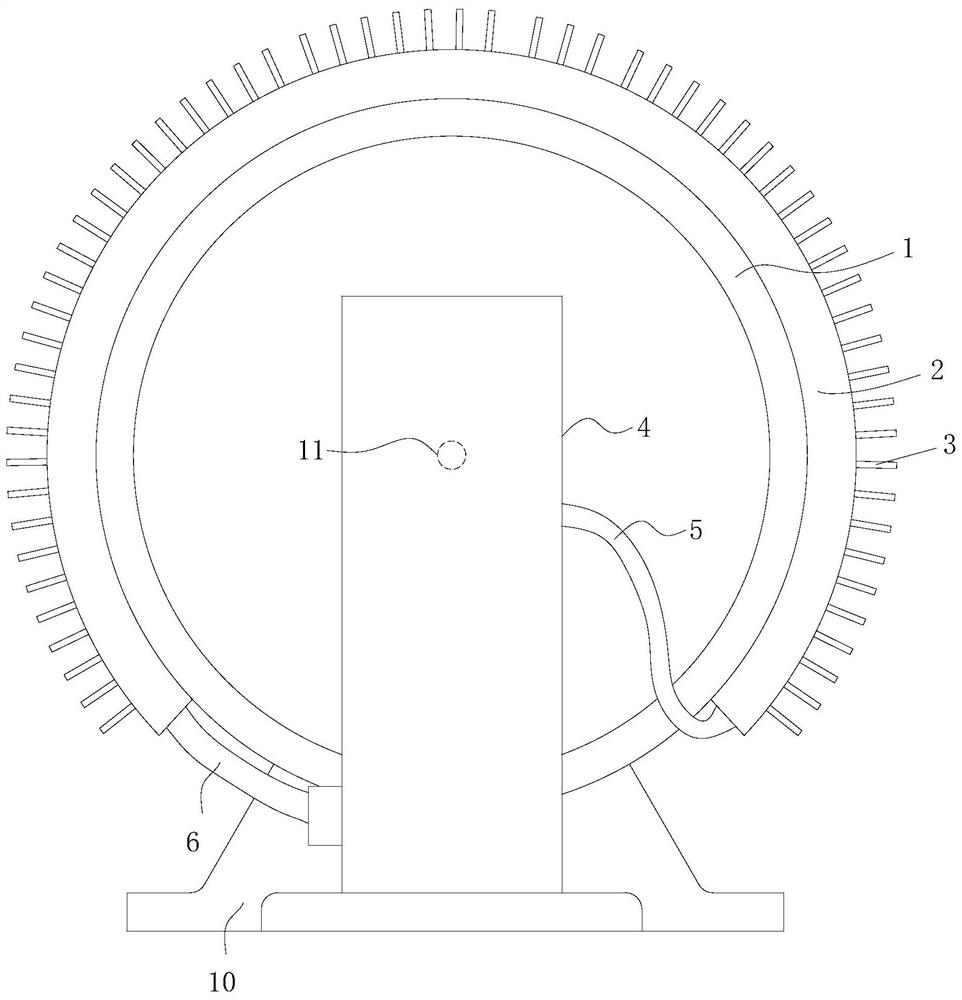
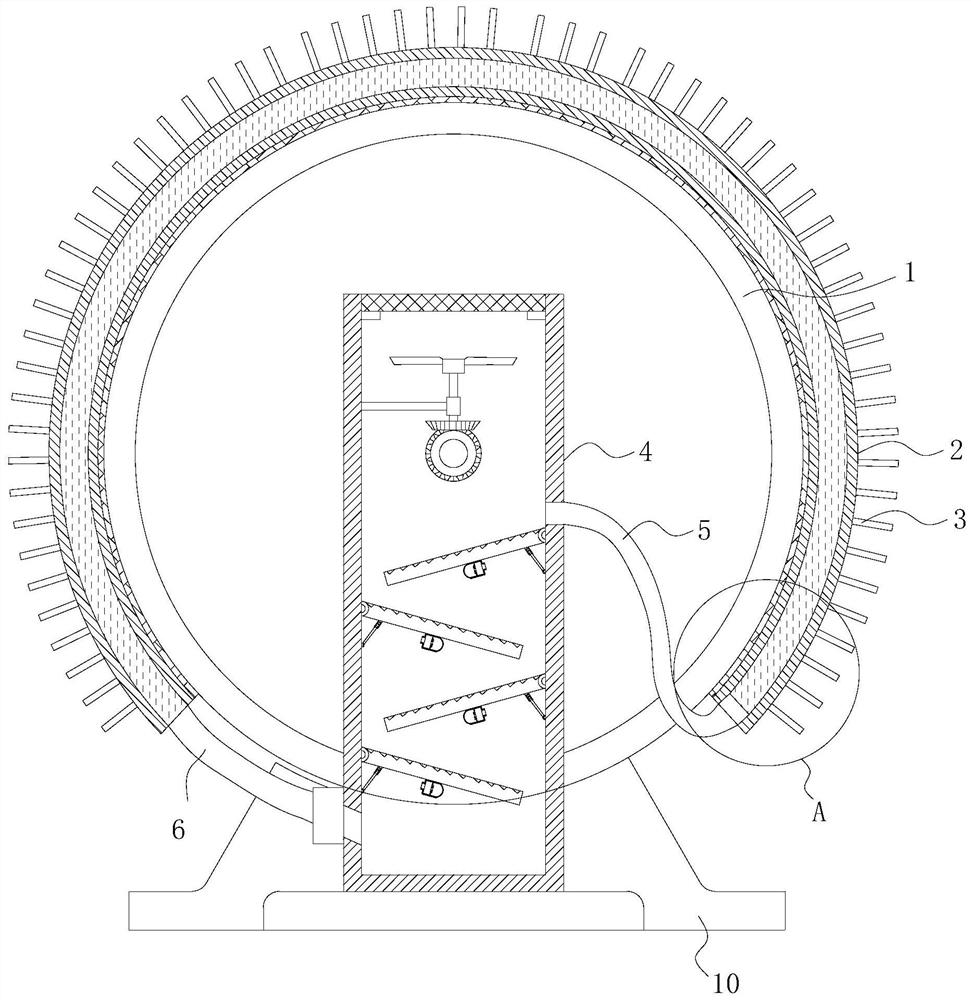
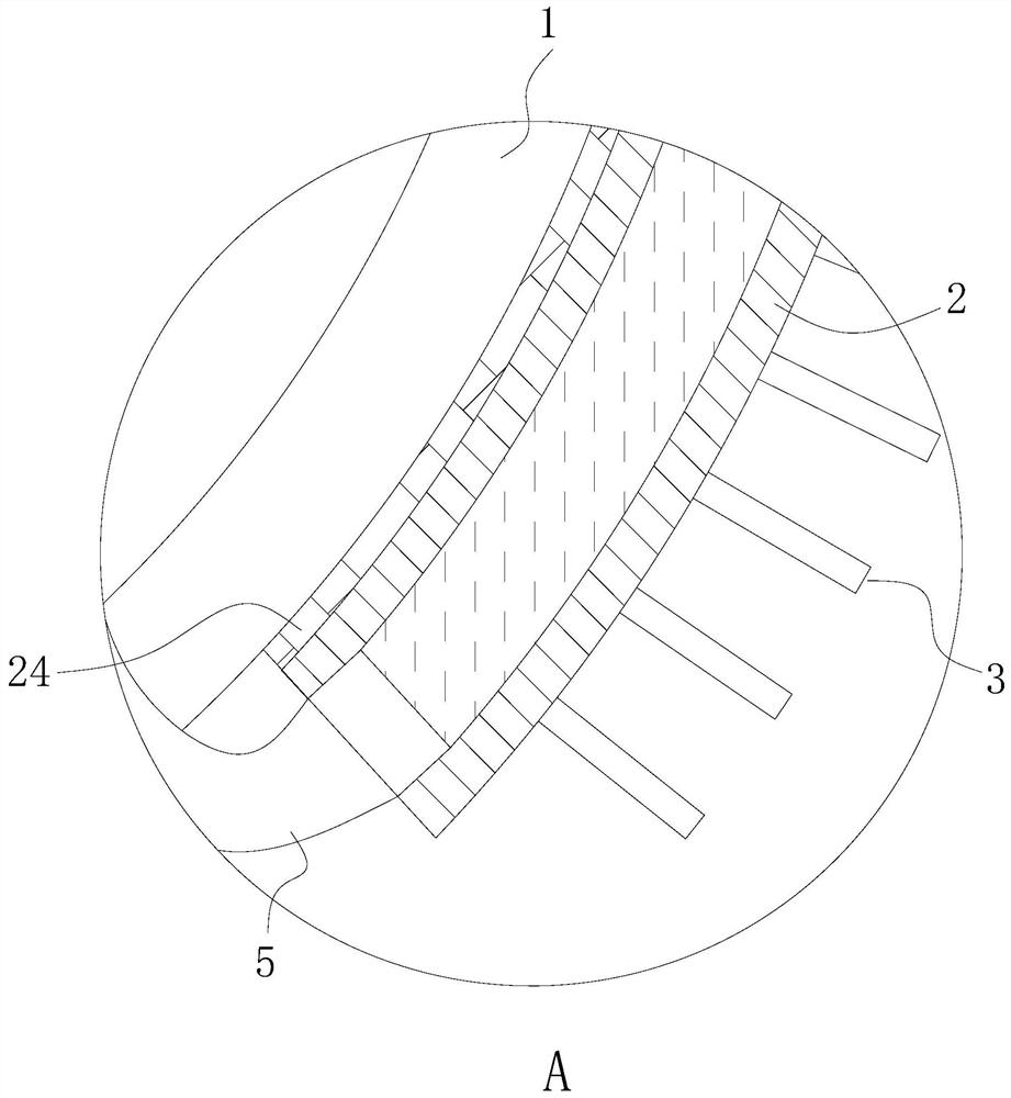
[0029] Please combine Figure 1 to Figure 7 , a three-phase motor with a cooling device, comprising a body 1 and a cooling device for cooling the body 1 . In this embodiment, the body 1 and the cooling device are installed on the base 10 . The base 10 can be an ordinary motor mounting frame to effectively support the body 1 . The heat dissipation device includes a heat exchange tank 2 and a water tank 4. The heat exchange tank 2 is fixed around the outer peripheral side of the body 1. In this embodiment, the side of the heat exchange tank 2 facing the body 1 as a whole is completely attached to the outside of the body 1 to cover the surface of the body. The heat dissipated in the heat-generating area is conducted to the inside of the heat exchange tank 2 . The heat exchange tank 2 can be fixed on the shell of the body 1 by screws, which is convenient for installation and disassembly. The side of the heat exchange tank 2 facing the body 1 is provided with a heat conduction l...

Embodiment 2

[0042] Please combine Figure 8 , this embodiment 2 is an improved solution of embodiment 1, specifically, the top of the deflector 8 is provided with a plurality of water blocking grooves 18 at equal intervals along its inclination direction, and the cross section of the water blocking groove 18 is a right triangle. The time for the water flow to pass through the top of the deflector 8 can be extended by the water blocking groove 18, and the water droplets in the water flow will splash when they flow out of the water blocking groove 18, so that the contact time between the water flow and the air becomes longer, and the cooling rate of the water flow is improved.


PUM


Abstract

The invention relates to the technical field of three-phase motors. The invention discloses a three-phase motor with a heat dissipation device. The three-phase motor comprises a machine body and a heat dissipation device for dissipating heat of the machine body, the heat dissipation device comprises a heat exchange groove and a water tank, the heat exchange groove is fixed to the peripheral side of the machine body in a surrounding mode, a heat conduction layer attached to a shell of the machine body is arranged on the side, facing the machine body, of the heat exchange groove, a plurality ofcooling fins are evenly arranged on the side, back on to the machine body, of the heat exchange groove, and cooling water used for heat exchange and cooling of the machine body is contained. Accordingto the three-phase motor with the heat dissipation device, a heat dissipation mode of a traditional three-phase motor is replaced, heat generated by operation of the motor body can be rapidly exchanged and cooled through the heat exchange grooves surrounding the outer side of the motor body, the heat dissipation efficiency and the heat dissipation effect of the motor body are improved, and normaloperation of the machine body is guaranteed. And meanwhile, an exhaust fan, a flow guide plate and an air blower in the water tank can improve the heat dissipation speed of the water after heat exchange, so that the heat exchange stability of the water in the water tank during each heat exchange cycle is guaranteed.

Description

technical field [0001] The invention relates to the technical field of three-phase motors, in particular to a three-phase motor with a cooling device. Background technique [0002] A three-phase motor means that when the three-phase stator windings of the motor (each with a phase difference of 120 degrees in electrical angle) are connected to the three-phase alternating current, a rotating magnetic field will be generated, and the rotating magnetic field will cut the rotor winding, thereby generating an induced current in the rotor winding ( The rotor winding is a closed path), and the current-carrying rotor conductor will generate electromagnetic force under the action of the rotating magnetic field of the stator, thereby forming an electromagnetic torque on the motor shaft, driving the motor to rotate, and the direction of rotation of the motor is the same as that of the rotating magnetic field. [0003] The body of the three-phase motor will generate a lot of heat during ...

Claims


Application Information

Patent Timeline
Patent Type & Authority Applications(China)
IPC IPC(8): H02K5/20H02K5/18H02K9/19
CPCH02K5/20H02K5/18H02K9/19
Inventor 徐文祥刘诗传余有龙彭书宏刘伟
Owner 六安华科电机有限公司
Learn More