Method and system for target detection using MIMO radar

A target detection and target technology, applied in the field of target detection, can solve problems such as no discussion, and achieve the effects of suppressing clutter, enhancing attraction, and enhancing signal clutter-to-noise ratio

Pending Publication Date: 2020-11-20
IEE INT ELECTRONICS & ENG SA +1
View PDF9 Cites 2 Cited by
  • Summary
  • Abstract
  • Description
  • Claims
  • Application Information

AI Technical Summary

Problems solved by technology

Finally, implementing virtual MIMO configurations while having beamforming capabilities is not discussed in the literature

Method used


Image

  • Method and system for target detection using MIMO radar
  • Method and system for target detection using MIMO radar
  • Method and system for target detection using MIMO radar

Examples


Embodiment Construction

[0052] I. Introduction

[0053] In the following, the same reference numerals will be used to designate similar elements. Unless otherwise indicated, any hardware element, algorithm step, or operation described herein (e.g., with respect to one embodiment) may be identical to one, more, or all other hardware elements described herein (e.g., with respect to another embodiment). , algorithm steps or operations are used in combination.

[0054] Although the present invention is described in the context of radar system design for automotive applications, the techniques described herein may be applied to any suitable system in automotive, security and spectrum sharing (with other radar systems / communication systems) scenarios.

[0055] In this disclosure, the operator ‖·‖ p defines l p norm. Matrix entries are represented by [ ] η,γ Definition, where n denotes the row index and γ denotes the column index. vector entries[ ] η Defined by an index n. E{} represents the expecta...


PUM


Abstract

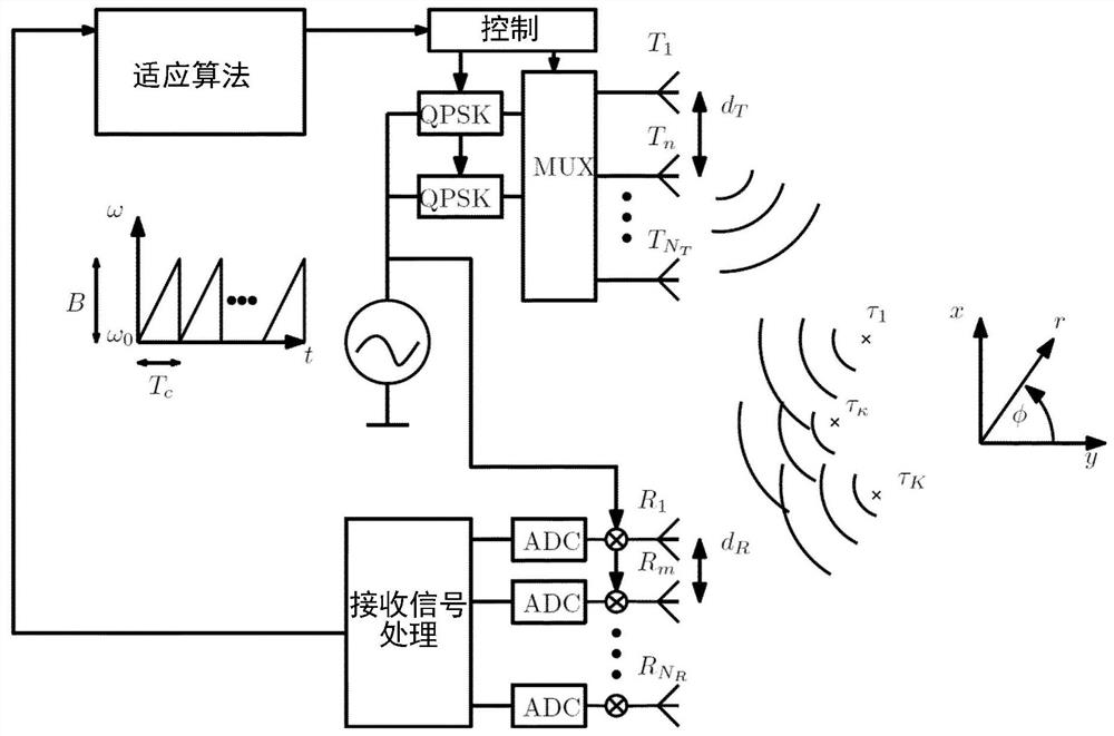
A method of sensing a target in a target detection system is provided. The method comprises processing circuitry, a multiplexer coupled to the processing circuitry and to a plurality NT of transmit antennas forming a sparse transmit uniform linear array, ULA, the multiplexer being configured to generate multiplexed and phase modulated transmit signals based on signals from a local oscillator, theprocessing circuitry being further coupled for receiving signals via a plurality of receive antennas forming a dense receive ULA. The method comprises transmitting the plurality of transmit signals via the transmit antennas so as to form a general radiation pattern corresponding to a block circulant probing signal matrix and receiving via the receive antennas receive signals resulting from backscattering of the plurality of transmit signals transmitted towards K targets. The method further comprises processing the received reflection signals to determine the presence, range and / or angular position of a target within a field of view of the transmit antennas. A corresponding target detection system and a vehicle incorporating the target detection system are also disclosed.

Description

technical field [0001] The present invention relates generally to object detection using multiple-input multiple-output (MIMO) radars such as those used in automotive applications, and more particularly to a method for transmit MIMO adaptive beamforming using block-cycle decomposition of cross-correlation matrices A method and system for object detection. Background technique [0002] In order to obtain the maximum amount of information about the scene around the vehicle (e.g., through multiple-input multiple-output (MIMO)), future automotive radar systems will communicate with several devices (transceiver device) to operate together. In order to be able to handle different signals, a form of orthogonality of the different codes transmitted by the transceiver is necessary. This can be done eg by switching certain devices on and off (time division multiplexing). [0003] In the following, previous publications ("references") listed at the end of this document are cited wit...

Claims


Application Information

Patent Timeline
Patent Type & Authority Applications(China)
IPC IPC(8): G01S13/931G01S13/42G01S7/282G01S13/32G01S13/34
CPCG01S7/282G01S13/325G01S13/34G01S13/42G01S13/931G01S7/0233G01S7/0234G01S7/35G01S13/426
Inventor C·哈梅斯B·S·米索尔拉玛拉奥B·奥特斯滕U·施罗德
Owner IEE INT ELECTRONICS & ENG SA
Why Eureka
Try Eureka