Vibration table for spheroidal graphite cast iron casting molding

A technology of nodular cast iron and vibrating table, which is applied to casting molding equipment, molding machines, and parts of molding machines. Simple, good shock absorption effect, not easy to damage the equipment

Inactive Publication Date: 2020-11-24
HANSHAN QINGXI DESHENG FOUNDRY FACTORY
View PDF1 Cites 1 Cited by
  • Summary
  • Abstract
  • Description
  • Claims
  • Application Information

AI Technical Summary

Problems solved by technology

[0004] Although the above-mentioned invention can squeeze the resin sand inside the box body to make it compact, when the pressure plate squeezes the box body, it cannot play

Method used


Image

  • Vibration table for spheroidal graphite cast iron casting molding
  • Vibration table for spheroidal graphite cast iron casting molding
  • Vibration table for spheroidal graphite cast iron casting molding

Examples


Embodiment 1

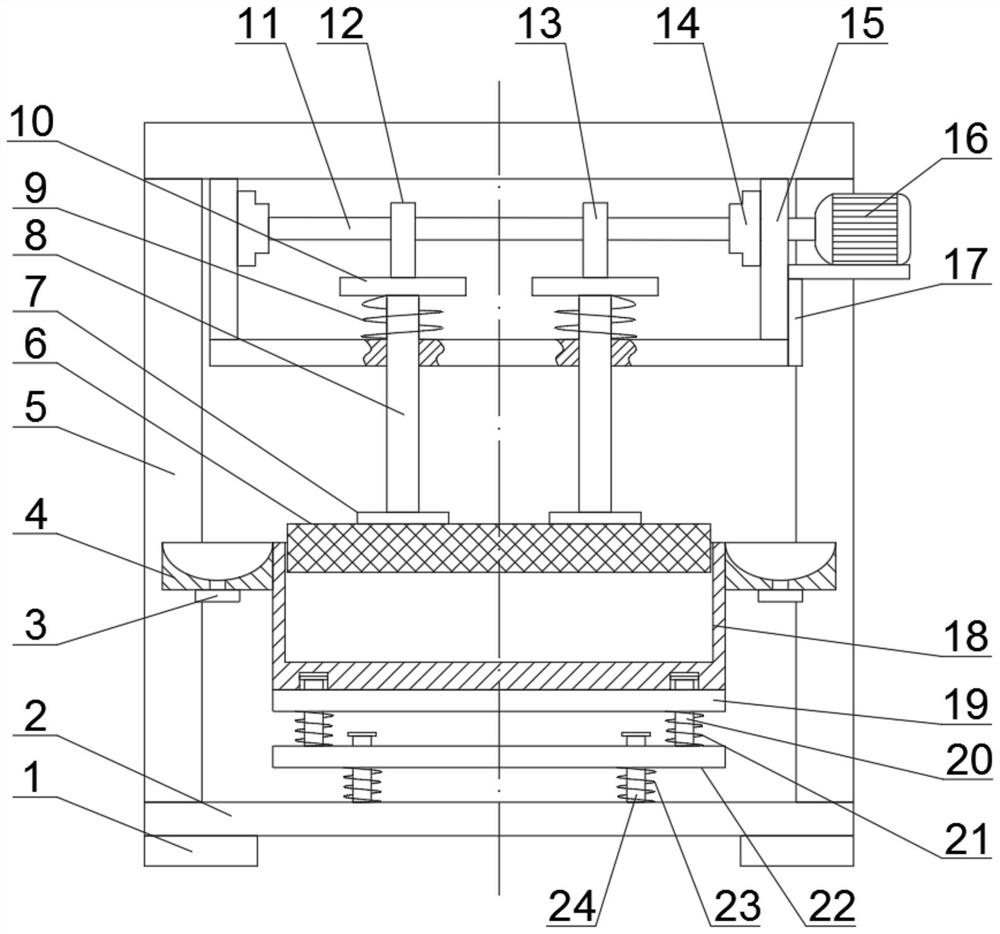
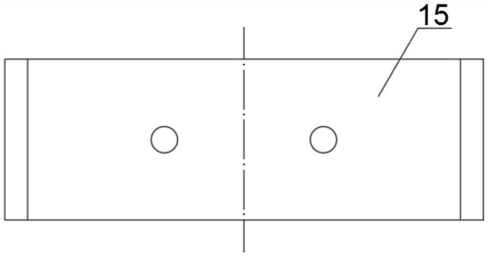
[0024] see Figure 1-3 , a vibrating table for modeling ductile iron castings, comprising a bottom plate 2, a support frame 5 is fixedly connected to both sides of the upper part of the bottom plate 2, a mounting seat 15 is fixedly connected to the bottom of the support frame 5, and a motor seat is fixedly connected to the right side of the mounting seat 15 17. A drive motor 16 is installed above the motor seat 17. The drive motor 16 is a geared motor with low vibration, low noise and good performance. The left side of the drive motor 16 is fixedly connected to a camshaft 11, and the camshaft 11 is connected to the Mounting seat 15 joint is fixedly connected with swivel seat 14, and described camshaft 11 is connected with swivel seat 14 in rotation, and described camshaft 11 middle left side is fixedly connected with first cam 12, and the right side of first cam 12 is installed with second camshaft. Cam 13, the first cam 12 and the second cam 13 are slidingly connected with a ...

Embodiment 2

[0026] In another embodiment of the present invention, the difference between this embodiment and the above-mentioned embodiment is that the lower part of the base plate 2 is fixedly connected with a kicker 1, and the kicker 1 heightens the distance between the base plate 2 and the horizontal plane, which is convenient for forklifts. Wait for it to be moved and transported.

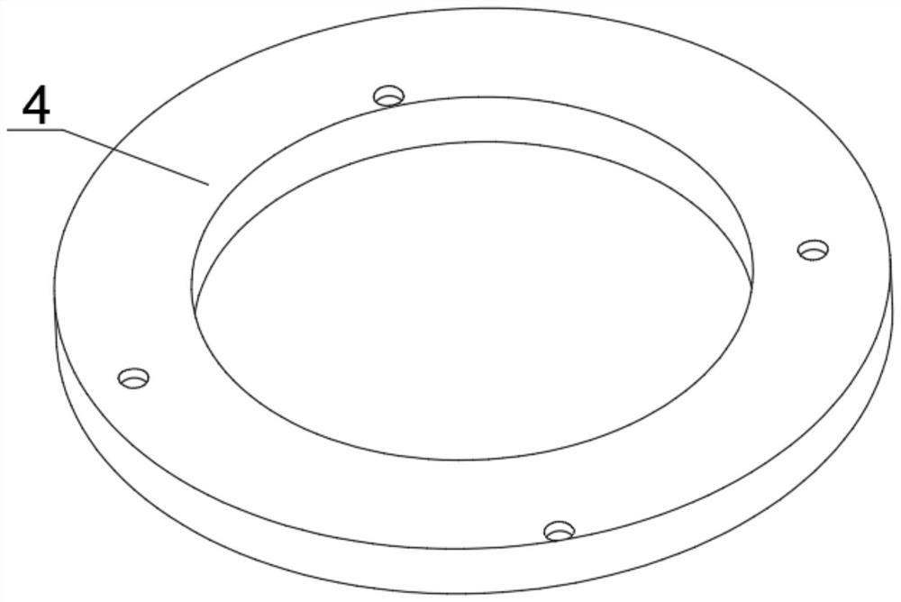
[0027] The working principle of the present invention is: the resin sand is poured into the casting box 18, and the driving motor 16 is started to drive the camshaft 11 to rotate, thereby driving the first cam 12 and the second cam 13 to rotate, so that the resin sand can be compacted by the pressing plate 6 , by arranging the second damping spring and the third damping spring, when the pressing plate 6 can squeeze the resin sand in the casting box 18, it can play the effect of damping and buffering, the damping performance is good, and it is not easy to damage the equipment; by setting the ring The colle...


PUM


Abstract

The invention discloses a vibration table for spheroidal graphite cast iron casting molding and belongs to the field of spheroidal graphite cast iron. The vibration table comprises a bottom plate, wherein a plurality of second guide columns are mounted in the middle of the upper part of the bottom plate, third springs are mounted outside the second guide columns, a second shock absorbing plate isfixedly connected above the third springs, a plurality of first guide columns are fixedly connected above the second shock absorbing plate, second springs are mounted outside the first guide columns,a first shock absorbing plate is fixedly connected above the second springs, a casting box is fixedly connected above the first shock absorbing plate, a collecting box is mounted outside the casting box, and a plurality of hole plugs are mounted at the bottom of the collecting box. By arranging the second and third shock absorbing springs, a shock-absorbing and buffering role is played when a pressing plate extrudes resin sand in the casting box, so that the vibration table is good in shock absorption and is unlikely to damage equipment. The vibration table is simple in structure, good in shock absorbing effect and high in practicality and is worth being applied and popularized.

Description

technical field [0001] The invention relates to the field of ductile iron castings, in particular to a vibrating table for modeling ductile iron castings. Background technique [0002] Ductile cast iron is a high-strength cast iron material developed in the 1950s. Its comprehensive performance is close to that of steel. It is based on its excellent performance that it has been successfully used to cast some complex stress, strength, toughness, and wear resistance. For parts with high performance requirements, nodular cast iron has rapidly developed into a cast iron material that is second only to gray cast iron and is widely used. Ductile cast iron needs to use a vibrating table during the casting process. [0003] The existing Chinese patent application publication number CN110788284A discloses a vibrating table for ductile iron casting molding, including a bottom plate and a table body; The left and right sides of the box are fixedly connected to the table body through e...

Claims


Application Information

Patent Timeline
IPC IPC(8): B22C15/06B22C19/00F16F15/067
CPCB22C15/06B22C19/00F16F15/067
Inventor 吕才木
Owner HANSHAN QINGXI DESHENG FOUNDRY FACTORY
Why Eureka
Try Eureka