Spaceflight electronic welding spot defect detection method based on improved Tiny-YOLOv3 network

A detection method and point defect technology, applied in biological neural network models, image analysis, image enhancement, etc., can solve problems such as difficulty in finding internal cracks and holes in solder joints, detection results vary from person to person, and difficulty in eliminating potential safety hazards. Achieve rapid and intelligent classification detection, facilitate popularization and application, and improve detection accuracy and efficiency

Pending Publication Date: 2020-11-24
HUAZHONG UNIV OF SCI & TECH +1
View PDF0 Cites 8 Cited by
  • Summary
  • Abstract
  • Description
  • Claims
  • Application Information

AI Technical Summary

Problems solved by technology

[0002] The stability and reliability of aerospace electronic equipment play a vital role in the development and application of the aerospace industry. The early detection of electronic solder joint defects is an important environment to ensure the stability and reliability of aerospace electronic equipment, and has become an important part of the aerospace industry. The key issue of industrial research, while the traditional manual inspection method lacks a unified quantitative standard for defect discrimination, and is inefficient, and is easily affected by subjective factors such as inspectors' work experience, visual fatigue, emotional changes, etc., which in turn leads to different inspection results. The consistency is poor, and it is impossible to avoid the occurrence of missed inspection accidents of solder joint defects, and it is difficult to meet the needs of large-scale industrial production
[0003] In addition, it is difficult to find defects such as internal cracks and holes in the solder joints by relying on manual inspection of the surface morphology of the solder joints, and it is difficult to eliminate the potential safety hazards caused by them.

Method used


Image

  • Spaceflight electronic welding spot defect detection method based on improved Tiny-YOLOv3 network
  • Spaceflight electronic welding spot defect detection method based on improved Tiny-YOLOv3 network
  • Spaceflight electronic welding spot defect detection method based on improved Tiny-YOLOv3 network

Examples


experiment example

[0054] The experimental computing platform is as follows: CPU is Intel(R) Core(TM) i7-8750H@2.2GHz; GPU is NVIDIA2070M; memory is 16GB; operating system is win10; the deep learning framework is Keras architecture based on tensorflow background.

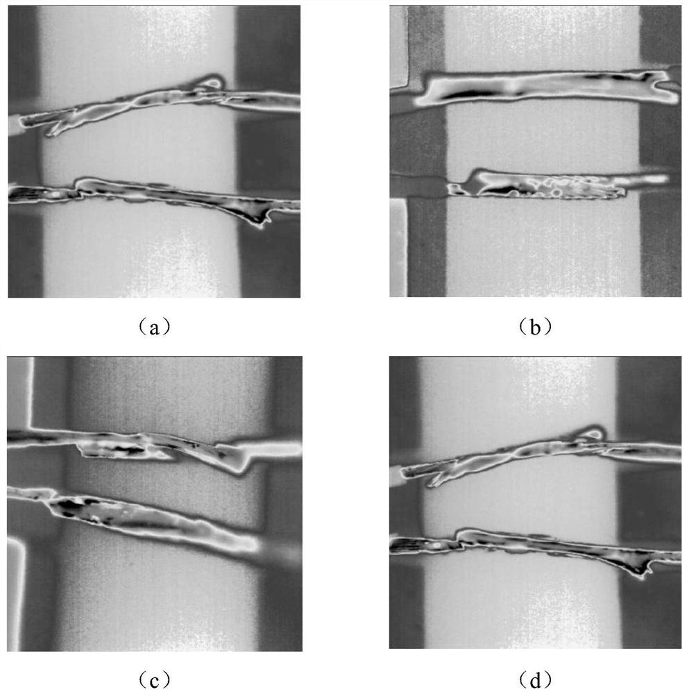
[0055] The obtained 383 infrared image samples of solder joints were cropped to obtain 383 infrared images of solder joints with a size of 416×416 pixels. Some images are as follows: figure 2 shown. Using the LabelImg image annotation software to label the positions and sizes of the three types of defects in the infrared images of solder joints, 383 xml format files containing the defect information of infrared images of solder joints were generated after labeling. The obtained xml format file is randomly divided into the training data set and the testing data set of the neural network according to the ratio of 9:1. The data set includes a total of 1274 objects of three types of defects: holes, breaches, and notches. . Using the Mo...


PUM


Abstract

The invention belongs to the related technical field of defect detection and discloses a spaceflight electronic welding spot defect detection method based on an improved Tiny-YOLOv3 network. The detection method comprises the following steps of (1) enhancing a network layer for feature extraction in Tiny_YOLOv3 by using a Mobileet network, replacing seven convolution and maximum pooling network layers in a Tiny _ YOLOv3 backbone network by using a lightweight network Mobileet to obtain an improved Tiny_YOLOv3 network; (2) inputting a welding spot infrared image with a known defect type into the improved Tiny_YOLOv3 network as a training data set of a sample so as to train and learn the improved Tiny_YOLOv3 network, thereby obtaining an improved Tiny _ YOLOv3 network model; and (3) inputting the infrared image of the welding spot sample to be detected into the improved Tiny_YOLOv3 network model so as to complete the detection of the welding spot defects. The spaceflight electronic welding spot defect detection method effectively improves spaceflight electronic welding spot defect detection accuracy.

Description

technical field [0001] The invention belongs to the technical field related to defect detection, and more specifically relates to a defect detection method for aerospace electronic solder joints based on the improved Tiny-YOLOv3 network. Background technique [0002] The stability and reliability of aerospace electronic equipment play a vital role in the development and application of the aerospace industry. The early detection of electronic solder joint defects is an important environment to ensure the stability and reliability of aerospace electronic equipment, and has become an important part of the aerospace industry. The key issue of industrial research, while the traditional manual inspection method lacks a unified quantitative standard for defect discrimination, and is inefficient, and is easily affected by subjective factors such as inspectors' work experience, visual fatigue, emotional changes, etc., which in turn leads to different inspection results. The consisten...

Claims


Application Information

Patent Timeline
Patent Type & Authority Applications(China)
IPC IPC(8): G06T7/00G06T7/10G06N3/04
CPCG06T7/0004G06T7/10G06T2207/10048G06T2207/20081G06T2207/30152G06N3/045
Inventor 孙博韩航迪付光辉黄垒司顺成赵继丁孟灵强廖广兰张许宁韩京辉
Owner HUAZHONG UNIV OF SCI & TECH
Why Eureka
Try Eureka