A Planar Endfire Circularly Polarized Antenna Without Delay Line Structure

A technology of circularly polarized antenna and wire structure, which is applied in the direction of antenna grounding switch structure connection, radiation element structure, etc., to achieve the effects of improving gain and radiation efficiency, reducing design complexity, and reducing energy loss

Active Publication Date: 2022-03-29
SOUTH CHINA UNIV OF TECH
View PDF6 Cites 0 Cited by
  • Summary
  • Abstract
  • Description
  • Claims
  • Application Information

AI Technical Summary

Problems solved by technology

[0007] The purpose of the present invention is to solve the design complexity of reducing the orthogonal magnetic dipole antenna, especially the design of the loop antenna structure; starting from the phase required to realize the circularly polarized radiation, the planar end-fire without delay line structure is proposed for the first time Circularly Polarized Antenna Design Scheme; Technical Problems of Realizing Circularly Polarized Radiation Simultaneously in Endfire and Backfire Directions

Method used


Image

  • A Planar Endfire Circularly Polarized Antenna Without Delay Line Structure
  • A Planar Endfire Circularly Polarized Antenna Without Delay Line Structure
  • A Planar Endfire Circularly Polarized Antenna Without Delay Line Structure

Examples


Embodiment Construction

[0034] The present invention will be described in further detail below in conjunction with the embodiments and the accompanying drawings, but the embodiments of the present invention are not limited thereto.

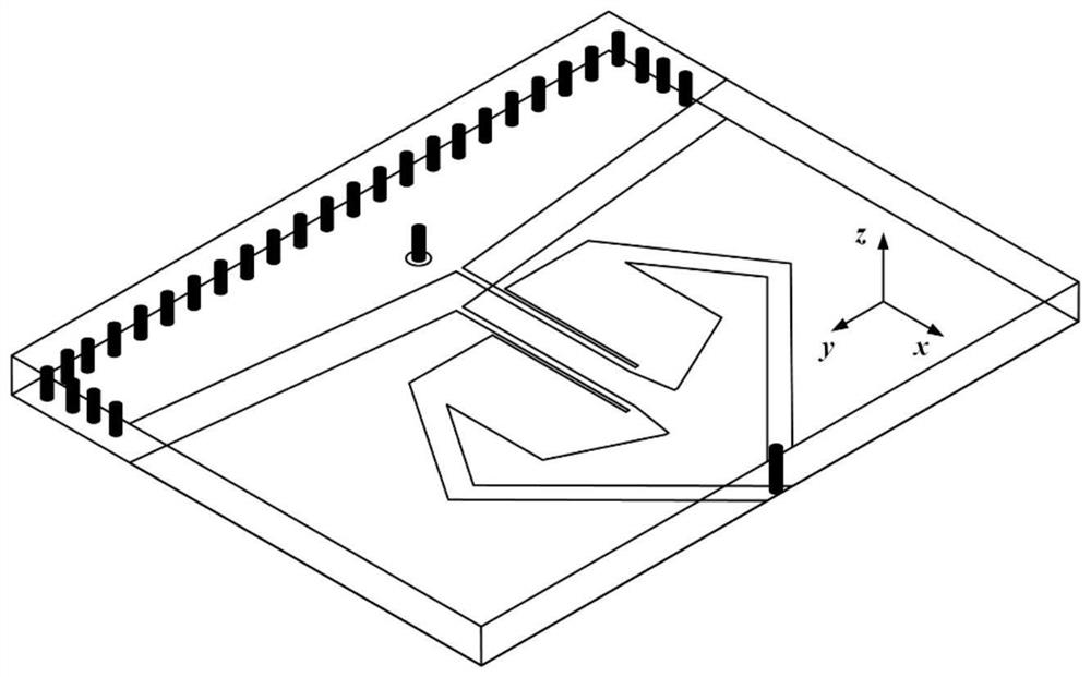
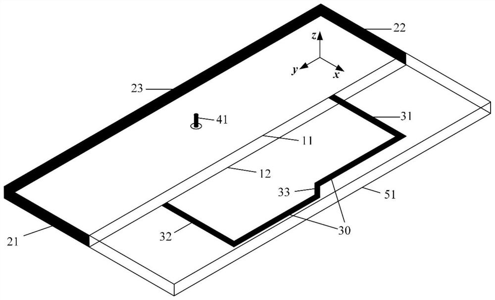
[0035] Such as Figure 2a and Figure 2b A planar end-fire circularly polarized antenna without a delay line structure is shown, including a magnetic dipole antenna 10, a loop antenna 30, a dielectric plate 51, and a feed coaxial 41;

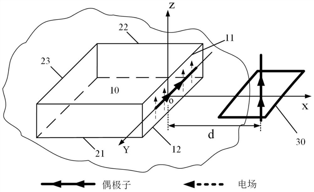
[0036] The magnetic dipole antenna provides the required vertical polarization component for circular polarization; the loop antenna 30 provides the corresponding horizontal polarization component;

[0037] The magnetic dipole antenna 10 includes an upper surface 11 and a lower surface 12 located on the upper and lower surfaces of the dielectric plate 51;

[0038] The first side 21, the second side 22, and the third side 23 of the magnetic dipole antenna 10 are all short-circuit structures, and the other side is opened for radiating ener...


PUM


Abstract

The invention discloses a planar end-fired circularly polarized antenna without a delay line structure, comprising a magnetic dipole antenna, a loop antenna, a dielectric plate, and a feeding coaxial; the magnetic dipole antenna includes The upper surface and the lower surface of the surface; the three connected sides of the magnetic dipole antenna are short-circuit structures, and the other side is opened for radiating energy; the upper surface and the lower surface of the loop antenna are respectively connected to the magnetic dipole The upper surface and the lower surface of the antenna; the upper surface and the lower surface of the loop antenna are connected by a short-circuit strip, thereby forming a closed loop structure; the feeding coaxial is located on the symmetry axis of the magnetic dipole antenna, and is used to generate an excitation signal .

Description

technical field [0001] The invention relates to the antenna field of electronic communication technology, and provides a planar end-fired circularly polarized antenna without a delay line structure. Background technique [0002] Circularly polarized antennas have good anti-interference ability, so they are widely used in various wireless systems. Traditional circularly polarized antennas, such as circularly polarized patch antennas, usually have side-firing radiation beam characteristics (that is, the direction of the main radiation beam is perpendicular to the plane of the dielectric plate), and it is difficult to achieve end-fire circular polarization (that is, the main radiation beam direction parallel to the plane of the dielectric plate). In recent years, literature (Wen-Jun Lu, Jing-Wen Shi, Kin-Fai Tong, and Hong-Bo Zhu, “PlanarEndfire Circularly Polarized Antenna Using Combined Magnetic Dipoles”, IEEE Antennas Wireless. Propag. Lett. , vol. 14, pp. 1263-1266, 201...

Claims


Application Information

Patent Timeline
Patent Type & Authority Patents(China)
IPC IPC(8): H01Q1/36H01Q1/38H01Q1/50
CPCH01Q1/38H01Q1/50H01Q1/36
Inventor 张文海薛泉廖绍伟车文荃
Owner SOUTH CHINA UNIV OF TECH
Why Eureka
Try Eureka