Gas-liquid distribution equipment

A gas-liquid distribution and equipment technology, applied in chemical instruments and methods, biological raw materials, chemical/physical processes, etc., can solve the problem of short contact time between gas phase and liquid phase, small gas-liquid two-phase spraying area, and gas-phase atomized liquid phase Poor capacity and other problems, to achieve the effect of avoiding uneven distribution, good liquid phase capacity, and promoting dissolution

Active Publication Date: 2020-11-27
CHINA PETROLEUM & CHEM CORP +2
View PDF10 Cites 1 Cited by
  • Summary
  • Abstract
  • Description
  • Claims
  • Application Information

AI Technical Summary

Problems solved by technology

[0007] In order to solve the problems existing in the prior art, such as poor gas atomization liquid phase ability, short contact time between gas phase and liquid phase, low gas solubility in liquid phase, small gas-liquid two-phase spraying area, large spraying droplets, uneven spraying, and gas Due to technical problems such as serious wall flow in the liquid distributor tube, the invention provides a gas-liquid distribution device to increase the contact between the gas-liquid two-phase, promote the atomization effect of the gas-liquid two-phase, and reduce the wall flow in the gas-liquid distributor tube Phenomenon

Method used


Image

  • Gas-liquid distribution equipment
  • Gas-liquid distribution equipment
  • Gas-liquid distribution equipment

Examples


Embodiment Construction

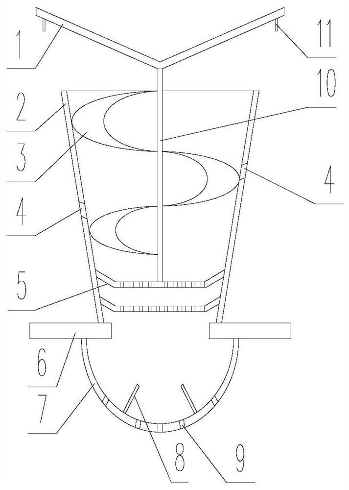
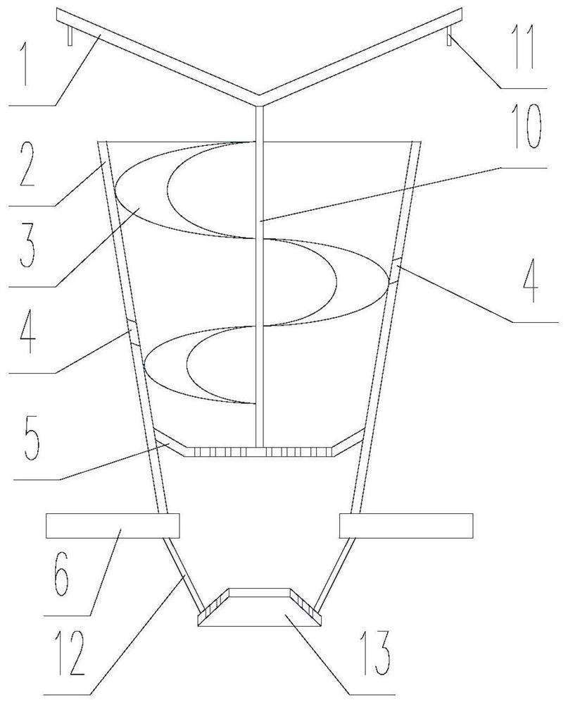
[0029] Such as figure 1 As shown, the gas-liquid distribution equipment of the present invention mainly includes a blocking cap 1, a mixing pipe 2 and a distribution plate 6 arranged from top to bottom; The lower end of the support rib 10 is fixed on the liquid collecting tray 5, the gap between the lower end of the baffle cap 1 and the upper end of the mixing tube 2 is used as a gas phase channel, and a full circle of vertically downward circular shroud 11 is arranged under the baffle cap 1, and the mixing tube 2 is an inverted tapered tube with both ends open, the upper end is the large end as the mixing tube inlet, the lower end is the small end as the mixing tube outlet, the lower end of the mixing tube 2 is fixed on the installation hole of the distribution plate 6, and the mixing tube wall is provided with The overflow hole 4 is used as a liquid phase channel, and the inner wall of the mixing tube is provided with a rotating guide vane 3, and the end of the rotating guid...


PUM


Abstract

The invention discloses gas-liquid distribution equipment. The gas-liquid distribution equipment comprises a blocking cap, a mixing pipe and a distribution disc which are arranged from top to bottom;the blocking cap is in a circular flat plate or conical umbrella shape and is arranged at the upper end of the mixing pipe, and a gap between the blocking cap and the upper end of the mixing pipe serves as a gas-phase channel; the mixing pipe is an inverted conical pipe with two open ends, wherein the upper end is a large end serving as a mixing pipe inlet, and the lower end is a small end servingas a mixing pipe outlet; the lower end of the mixing pipe is fixed on a mounting hole of the distribution disc; overflow holes are formed in the pipe wall of the mixing pipe as liquid phase channels;the inner wall of the mixing pipe is provided with a rotary guide vane; the tail end of the rotary guide vane and the inner wall of the mixing pipe in front of an outlet of the mixing pipe are provided with one or two or more layers of liquid collecting discs; the liquid collecting discs are concave flat-bottom discs and are fixedly connected with the wall of the mixing pipe through convex concave edges; and distribution holes are uniformly distributed in the bottoms of the liquid collecting discs to allow a gas phase and a liquid phase to pass through. According to the invention, gas-liquidtwo-phase contact can be enhanced, the gas-liquid two-phase atomization effect is promoted, and the wall flow phenomenon in the overflow pipe is reduced.

Description

technical field [0001] The invention belongs to the field of petroleum refining and chemical equipment, and relates to a reactor internal component, in particular to a gas-liquid distribution equipment. Background technique [0002] In recent years, with the gradual upgrading of petrochemical product quality standards and increasingly stringent environmental protection regulations, hydrogenation technology has played an increasingly important role in the oil refining industry. In order to improve economic efficiency and meet the requirements of environmental protection, oil refining enterprises have rapidly expanded the hydrotreating capacity of various oil products. [0003] The key core equipment for hydroprocessing is the hydrogenation reactor. Inside the hydrogenation reactor, a mixture of a certain proportion of hydrogen (gas phase) and raw oil (liquid phase) is used at a certain temperature and pressure to complete various hydrogenation processes. hydrogen reaction. ...

Claims


Application Information

Patent Timeline
Patent Type & Authority Applications(China)
IPC IPC(8): B01J8/02
CPCB01J8/0278B01J2208/00911Y02P30/20
Inventor 邓矛
Owner CHINA PETROLEUM & CHEM CORP
Why Eureka
Try Eureka