[0027] The application will be further described in detail below in conjunction with the accompanying drawings. It is necessary to point out that the following specific implementations are only used to further illustrate the application and cannot be understood as limiting the scope of protection of the application. Those skilled in the art can follow The above application content makes some non-essential improvements and adjustments to this application.
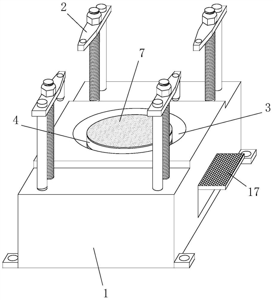
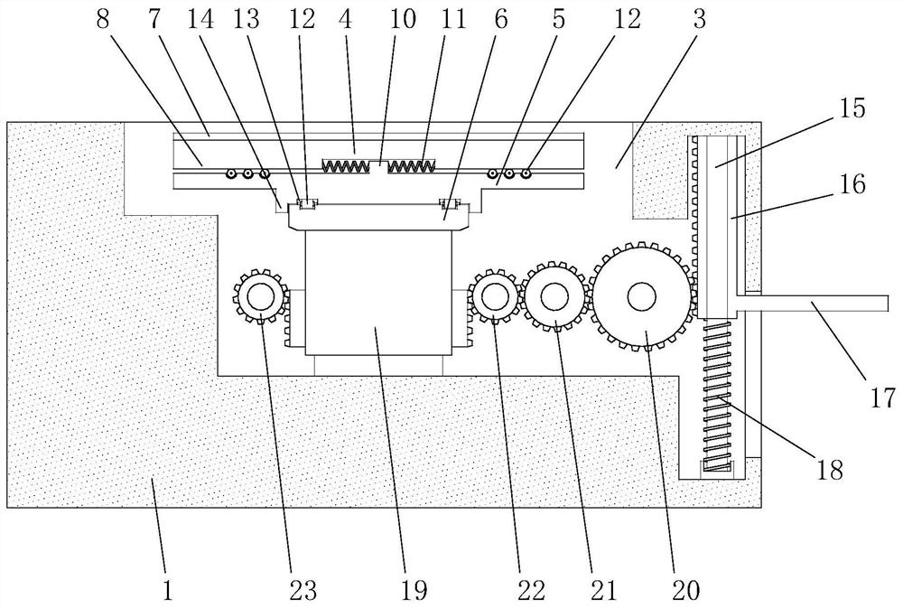
[0028] Combine Figure 2 to Figure 7 As shown, a marine diesel engine cylinder head production equipment includes a base 1, a mounting hole is provided at the bottom of the base 1 for fixing, and a number of fixing mechanisms 2 are installed on the top surface of the base 1. The fixing mechanism 2 is used to perform the cylinder head Positioning and locking, its structure can be composed of a screw, a sliding rod, a compression block and an anti-off cap. The screw is vertically movably installed on the base 1 and can be rotated, while the sliding rod is fixed and installed vertically, and the compression block has a screw hole And a cylindrical hole, the screw thread is matched with the screw hole, the sliding rod passes through the cylindrical hole, so that the screw can be rotated to realize the up and down movement of the compression block. The end of the compression block is provided with a compression column whose size is the same as that on the cylinder head. The four positioning holes are matched, the fixing mechanism 2 has four, and it can be inserted into the four positioning holes to realize the positioning and locking of the cylinder head.
[0029] In the above-mentioned fixing mechanism 2, in order to facilitate the judgment of whether the position of the cylinder head is accurate, a laser head can be provided at the bottom end of the pressure column to emit a laser beam vertically downwards. By observing whether the points irradiated by the laser are all in the positioning hole, This judges whether the position of the cylinder head is accurate. If it is accurate, press the compression block down for positioning. If it is not accurate, you need to fine-tune the position of the cylinder head. Refer to the following for the specific fine-tuning scheme.
[0030] In the present invention, the base 1 is provided with a cavity 3 with an opening at the top. The opening is preferably circular. The cavity 3 is provided with a supporting mechanism. The supporting mechanism includes a supporting plate 4, a linear adjusting plate 5 and a rotating adjusting plate. 6. There is a gap of 3-5cm between the edge of the support plate 4 and the opening wall. The bottom surface of the support plate 4 and the top surface of the linear adjustment plate 5 are linearly movably connected, that is, the support plate 4 can move in a straight line on the top surface of the linear adjustment plate 5 , The bottom surface of the linear adjustment disc 5 and the top surface of the rotary adjustment disc 6 are rotatably connected, that is, the linear adjustment disc 5 can rotate on the top surface of the rotary adjustment disc 6; in addition, the supporting mechanism is connected with a driving mechanism, which is used to drive the supporting mechanism in Move between the first position and the second position. The first position is that the support mechanism extends out of the cavity 3 and the top surface of the support plate 4 is higher than the top surface of the base 1, and the second position is that the support mechanism is stored in the cavity 3 and the support plate 4 is on top. The surface is lower than the top surface of the base 1. When there is no need to fine-tune the position of the cylinder head, the support mechanism is in the second position, and the cylinder head is supported by the top surface of the cylinder head, which can provide a stable positioning effect. When fine adjustment of the cylinder head is required, the support mechanism is in the first position to support The disc plays the role of supporting the cylinder head. At this time, the cylinder head can be moved directly to fine-tune the position and angle.
[0031] In the present invention, the top surface of the support plate 4 is covered with a friction layer 7, and the friction layer 7 may be a wear-resistant rubber material to increase the friction force while avoiding the wear of the cylinder head surface.
[0032] In the present invention, the bottom surface of the support plate 4 is provided with two protrusions 8 along the same diameter. The two protrusions 8 are symmetrical to each other and separated by a certain distance. The top surface of the linear adjustment plate 5 is provided with a groove 9 along the diameter. , The width of the groove 9 matches the width of the protruding strip 8, a fixed block 10 is arranged in the middle of the groove 9, and a return spring 11 is connected to both sides of the fixed block 10, and a number of The rolling direction of the roller 12 is consistent with the direction of the groove 9. The protrusion 8 is embedded in the groove 9 and is in rolling contact with the roller 12, and the outer ends of the two return springs 11 abut against the inner ends of the protrusion 8. When the support plate 4 is pushed in a specific direction (consistent with the direction of the groove 9, in order to facilitate the determination of the direction, the surface of the support plate 4 can be marked), the support plate 4 will translate relative to the linear adjustment plate 5, and two return springs 11 One will compress and the other will stretch. When the thrust is removed, it will return to the intermediate initial position under the action of the return spring 11. The stiffness coefficient of the return spring 11 should not be too large, as long as it can push the support plate 4 to return.
[0033] In particular, the top surface of the linear adjusting disc 5 is also provided with a number of rollers 12 on both sides of the groove 9 respectively for direct rolling contact with the bottom surface of the support plate 4, and the roller 12 and the roller 12 in the groove 9 are not on the same line , And work together to stabilize and support.
[0034] In the present invention, the bottom surface of the linear adjustment disc 5 is provided with concentric ring grooves 13, and there are two concentric ring grooves 13. On the other hand, a number of rollers 12 are provided on the top surface of the rotary adjusting plate 6 along the circumferential direction, and the rollers 12 are exactly embedded in the concentric ring groove 13 and roll along the concentric ring groove 13. When the support plate 4 is rotated, the support plate 4 will drive the linear adjustment plate 5 to rotate synchronously, that is, the linear adjustment plate 5 rotates relative to the rotary adjustment plate 6. During the rotation, the roller 12 rolls along the concentric ring groove 13.
[0035] It should be noted that the rollers 12 provided at each position described above use rolling friction instead of sliding friction to reduce friction, and the adjustment process is more labor-saving.
[0036] In the present invention, the driving mechanism adopts a manual driving mode, because the cost can be saved, and the adjustment process is more intuitive, convenient, and more user-friendly. Of course, it can also be driven by electricity, for example, directly using an electric telescopic rod controlled by a controller.
[0037] This embodiment introduces a manual driving method in detail: the driving mechanism includes a guide rod 15, a cover plate 16, a foot pedal 17, a support spring 18, a movable seat 19 and a reduction gear set. The guide rod 15 may have two, and the guide rod 15 is vertically arranged in the cavity 3, the cover plate 16 is movably arranged on the guide rod 15, the cover plate 16 can move up and down along the guide rod 15, the foot pedal 17 is fixedly connected to the side of the cover plate 16, and the foot pedal 17 extends horizontally from the side of the base 1, leaving a space for the foot pedal 17 to move up and down on the side of the base 1. The support spring 18 is arranged on the guide rod 15 and the top end of the support spring 18 contacts the bottom end of the cover plate 16 to move the seat 19 is connected to the bottom end of the rotating adjustment plate 6, the side of the movable seat 19 and the side of the cover plate 16 are both equipped with racks, the power input end of the reduction gear set is meshed and connected with the side of the cover plate 16, and the reduction gear set The power output end is meshingly connected with the side of the movable seat 19. Specifically, the reduction gear set is composed of a first gear 20, a second gear 21, and a third gear 22 whose radius is gradually reduced. The first gear 20, the second gear 21 and the third gear 22 are sequentially meshed and connected, and the reduction gear The group is meshed and connected with the side of the cover plate 16 through the first gear 20, and meshed and connected with the side of the movable seat 19 through the third gear 22.
[0038] It should be noted that the deceleration ratio of the reduction gear needs to be selected, so that when the support spring 18 supports the cover plate 16 at the highest point of the guide rod 15, the support mechanism is exactly at the first position; when the foot pedal 17 drives the cover plate When 16 moves down to the lowest point of the guide rod 15, the support mechanism is just at the second position.
[0039] Further, the driving mechanism further includes an auxiliary gear 23, which is meshed and connected with the movable base 19, and the connection position is exactly opposite to the connection position of the reduction gear set on the movable base 19. The auxiliary gear 23 can play a role in increasing the movement stability of the movable seat 19.
[0040] Rejoin Figure 8 As shown, the working principle of the present invention is:
[0041] First transport the cylinder head to the top surface of the base 1 through the lifting equipment. At this time, the support mechanism is in the first position. The cylinder head is in direct contact with the top surface of the base 1, which is difficult to move. However, due to the deviation of the accuracy of the lifting equipment, although the deviation is The amount is not large, but it is inevitable to fine-tune the position of the cylinder head. Only after the position is accurate, can it cooperate smoothly with other equipment to ensure the quality of cutting.
[0042] Open the laser head at the bottom of the pressure column before fine-tuning, and compare and fine-tune by observing the position of laser irradiation. When fine-tuning, you only need to pedal the pedal 17 and the pedal 17 will drive the cover plate 16 to move down the guide rod 15 to the bottom end, the support spring 18 is compressed, and the cover plate 16 will drive the first gear 20, The second gear 21 and the third gear 22 rotate in turn, and the reduction gear set finally drives the movable seat 19 to move upwards. The reduction gear set saves effort, controls and reduces the displacement, so that the power of the feet can fully support the cylinder head. ; After the movable seat 19 rises, the supporting mechanism is driven to the second position as a whole to support the cylinder head, and the cylinder head is separated from the top surface of the base 1. At this time, compare and fine-tune according to the laser irradiation position. The specific fine-tuning method is:
[0043] Turn the cylinder head first to make the support plate 4 and the linear adjustment plate 5 rotate synchronously, so that the cylinder head and the support plate 4 can move linearly in the direction of the designated position (the direction of the groove 9 is consistent with the direction of the designated position), and then push the cylinder head, Make the cylinder head and the support plate 4 move toward the designated position. After moving to the designated position, release the pedal 17, under the action of the support spring 18, the cover plate 16 is located at the highest point of the guide rod 15, and the support mechanism returns To the first position, the cylinder head is again supported by the top surface of the base 1. After the support plate 4 is separated from the cylinder head, it will automatically return to the center initial position under the action of the return spring 11, and then pedal 17 again to make the support Disk 4 supports the cylinder head again (the support position changes at this time. Because the size of the cylinder head is larger and the support plate has enough support area, a small change in the support position will not cause the cylinder head to roll over). Rotate the cylinder head to irradiate the laser into each positioning hole. If not, you can fine-tune again. After the fine-tuning process is over, the position and angle are appropriate. Press the compression block to complete the positioning work, and then perform the cylinder head pin hole 100, Cutting process of sand cleaning hole 200 and injector pipe hole 300.
[0044] In the above process, if there is a special situation where the position deviation is large, due to the limited relative displacement of the support plate 4 with respect to the linear adjustment plate 5, one push may not reach the specified position. At this time, you only need to support the cylinder again on the support plate 4. When covering, just continue to push the cylinder head, repeat the process until it reaches the designated position, and then perform the final angle adjustment.
[0045] The above-mentioned embodiments only express several implementation modes of the present invention, and the description is relatively specific and detailed, but it should not be understood as a limitation to the patent scope of the present invention. It should be pointed out that for those of ordinary skill in the art, without departing from the concept of the present invention, several modifications and improvements can be made, and these all fall within the protection scope of the present invention.