
Plate negative pressure machining equipment

A processing equipment and negative pressure technology, which is applied in the field of plate negative pressure processing equipment, can solve problems such as complicated and inconvenient operation procedures, affect work efficiency, and single structure, achieve great improvement and use value, increase service life, and improve work efficiency. efficiency effect

Inactive Publication Date: 2020-11-27
周珍梅
View PDF8 Cites 0 Cited by
  • Summary
  • Abstract
  • Description
  • Claims
  • Application Information

AI Technical Summary

Problems solved by technology

[0002] The earliest boards were solid wood boards for carpentry, which were used to make furniture or other living facilities. Nowadays, with the development of science and technology, the definition of boards is very broad. There are boards of different materials in furniture manufacturing, construction, and processing industries. Boards are classified according to Material classification can be divided into two categories: solid wood board and wood-based board; according to the classification of molding, it can be divided into solid board, plywood, fiberboard, decorative panel, fireproof board, particle board, etc., and the use requirements are different, so it usually involves the adjustment of the board. Cutting processing, the existing plate cutting and processing equipment has a relatively simple structure. Usually, when a plate is cut into multiple strips, it can only be cut one by one. It pollutes the air environment, and at the same time, pay attention to the debris during cutting. The excessive accumulation of debris affects the cutting effect and needs to be cleaned at any time, which indirectly affects work efficiency. Therefore, it is necessary to propose a plate negative pressure processing equipment to solve this problem. question

Method used


Image

  • Plate negative pressure machining equipment
  • Plate negative pressure machining equipment
  • Plate negative pressure machining equipment

Examples


Embodiment Construction

[0021] In order to make the technical means, creative features, goals and effects achieved by the present invention easy to understand, the present invention will be further described below in conjunction with specific embodiments.

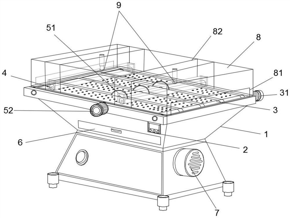
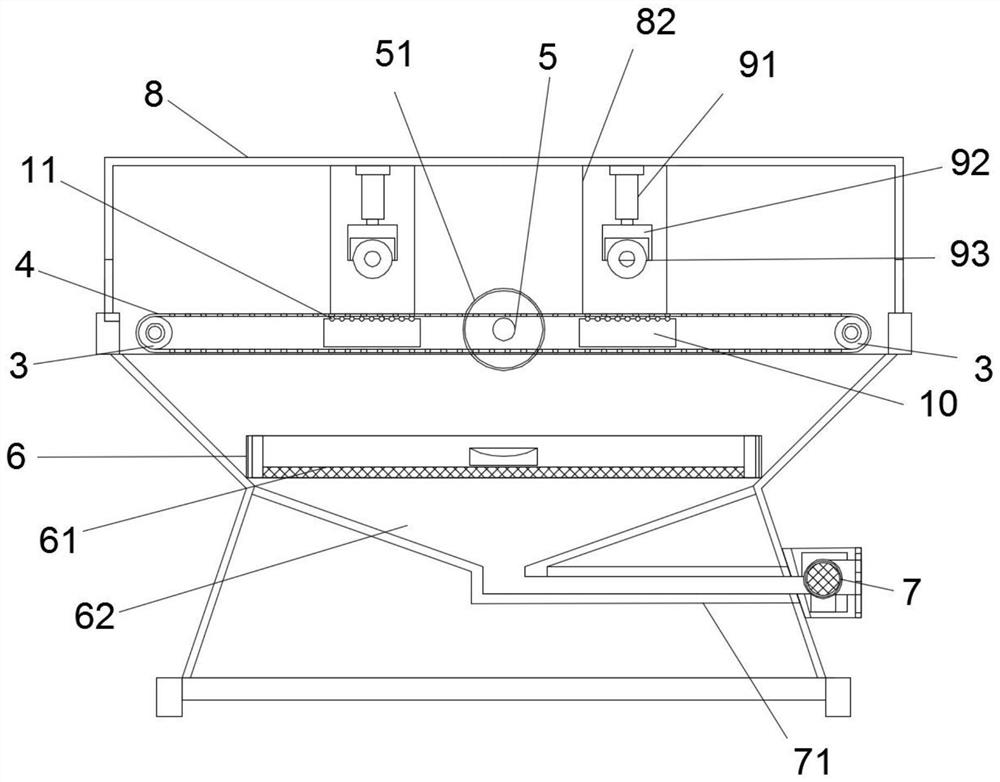
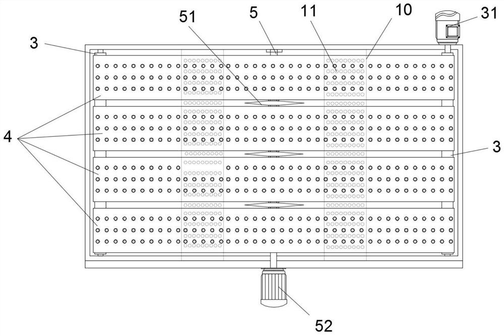
[0022] Such as Figure 1-3 As shown in the figure, the present invention provides a technical solution of plate negative pressure processing equipment: its structure includes a box body 1 and a controller 2 installed on the front side of the box body 1, and the left and right sides of the box body 1 are respectively rotatably connected. Conveyor rollers 3 are arranged, and several conveyer belts 4 are connected between the two conveyer rollers 3, and a rotating shaft 5 is interspersed in the middle of the conveyer belt 4, and several cutting blades 51 are not connected in the rotating shaft 5, each The cutting blades 51 are respectively arranged between each of the conveyor belts 4, and the middle part of the box body 1 is slidably connected with ...


PUM


Abstract

The invention relates to the technical field of plate machining, in particular to plate negative pressure machining equipment. The plate negative pressure machining equipment structurally comprises abox body and a controller installed on the front side of the box body, conveying rollers are rotationally connected to the left side and the right side of the upper side of the box body correspondingly, a plurality of conveying belts are connected between the two conveying rollers, a rotating shaft is inserted into the middles of the conveying belts in a penetrating mode, a plurality of cutting blades are not connected into the rotating shaft, the cutting blades are arranged between the conveying belts correspondingly, a dust collecting groove is slidably connected to the middle of the box body, the dust collecting groove is formed below the cutting blades and the conveying belts, a dust filter screen is installed at the bottom of the dust collecting groove, a negative pressure hopper cavity is formed below the dust filter screen, plates are conveyed through the plurality of arranged conveying belts, all cutting blades in the middles of the plates are cut at the same time, efficient cutting machining of the plates is achieved, dust can be collected through the dust collecting groove and the dust filter screen below the conveying belts, and cleaning is convenient.

Description

technical field [0001] The invention relates to the technical field of sheet material processing, in particular to a sheet material negative pressure processing equipment. Background technique [0002] The earliest boards were solid wood boards for carpentry, which were used to make furniture or other living facilities. Nowadays, with the development of science and technology, the definition of boards is very wide. There are boards of different materials in furniture manufacturing, construction industry, processing industry, etc. Material classification can be divided into two categories: solid wood board and wood-based board; according to the shape classification, it can be divided into solid board, plywood, fiberboard, decorative panel, fireproof board, particle board, etc., and the use requirements are different, so it usually involves the adjustment of the board. Cutting processing. The existing plate cutting and processing equipment has a relatively simple structure. Us...

Claims


Application Information

Patent Timeline
IPC IPC(8): B27C5/02B27C5/06B27G3/00
CPCB27C5/02B27C5/06B27G3/00
Inventor 周珍梅
Owner 周珍梅
Learn More