Cutting method of glass substrate and manufacturing method of glass substrate

A technology for glass substrates and cutting methods, applied in glass manufacturing equipment, glass cutting devices, manufacturing tools, etc., can solve the problems of reduced cutting accuracy, reduced glass substrate accuracy, time-consuming, etc., and achieves the effect of good accuracy

Inactive Publication Date: 2017-12-12
ASAHI GLASS CO LTD
View PDF4 Cites 0 Cited by
  • Summary
  • Abstract
  • Description
  • Claims
  • Application Information

AI Technical Summary

Problems solved by technology

Therefore, it takes time to polish the cutting surface
[0007] In addition, it is necessary to blow compressed gas (assist gas) to the glass substrate immediately after laser irradiation, so the position of the glass substrate is likely to shift, and the cutting accuracy may decrease.
[0008] According to the method for cutting a glass substrate proposed in Patent Document 2, the position of the glass substrate is displaced by the pressure of the assist gas, and there is a problem that the cutting accuracy sometimes decreases.
In addition, depending on the energy density of the laser beam, the amount of thermal deformation of the local glass may increase to cause cracks in the glass substrate.
In addition, the molten glass removed by the assist gas adheres to and solidifies on the cut surface or its surroundings, so it takes time to perform a grinding process to remove it.

Method used


Image

  • Cutting method of glass substrate and manufacturing method of glass substrate
  • Cutting method of glass substrate and manufacturing method of glass substrate
  • Cutting method of glass substrate and manufacturing method of glass substrate

Examples


experiment example 1

[0070] In this experimental example, the glass substrate was cut while changing the energy density of the laser light and the moving speed of the laser irradiation area relative to the glass substrate, and the cut surface of the cut glass substrate was evaluated.

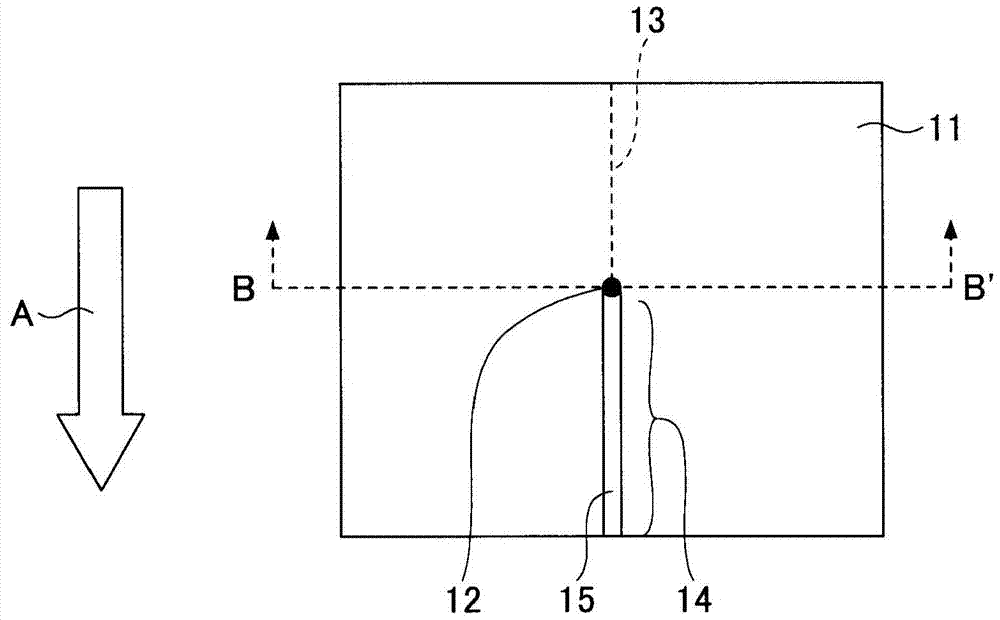
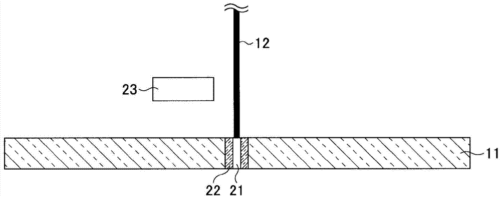
[0071] When cutting glass substrates, by figure 1 In the shown configuration, for a glass substrate (manufactured by Asahi Glass Co., Ltd., trade name: AN100) comprising an alkali-free borosilicate glass with a length of 100 mm, a width of 100 mm, and a plate thickness of 0.1 mm, the glass substrate was transported at a predetermined transport speed. CO is irradiated along the predetermined cutting line with a spot diameter of about 0.3 mm and a predetermined energy density. 2 Laser laser. When cutting, the peripheral temperature (environmental temperature) of the glass substrate was room temperature (25° C.).

[0072] For the glass substrate after cutting, the case where it cannot be cut is evaluated as C; althou...

experiment example 2

[0085] In this experimental example, except that the plate thickness of the glass substrate to be cut was 0.2 mm, the energy density of the laser light and the moving speed of the irradiation area of ​​the laser light relative to the glass substrate were changed in the same manner as in Experimental Example 1 to cut the glass substrate. The cut surface of the cut glass substrate was evaluated.

[0086] The results are shown in Table 2, Figure 5 middle. Figure 5 It is a figure which plotted the result of Table 2.

[0087] Table 2

[0088]

[0089] exist Figure 5 In the shown figure, the straight line X is also the straight line of E=50×t×v (t=0.2 mm) mentioned above.

[0090] In addition, the straight line Y shows the minimum value of the moving speed (here, the conveying speed of the glass substrate) of the irradiated region of the laser light relative to the glass substrate in which precipitates are generated in the cooling process, and in this case, it is 144 (m / ...

experiment example 3

[0093] In this experimental example, except that the plate thickness of the glass substrate to be cut was 0.3 mm, the energy density of the laser light and the moving speed of the irradiation area of ​​the laser light relative to the glass substrate were changed in the same manner as in Experimental Example 1 to cut the glass substrate. The cut surface of the cut glass substrate was evaluated.

[0094] The results are shown in Table 3, Figure 6 middle. Figure 6 It is a figure which plotted the result of Table 3.

[0095] table 3

[0096]

[0097] exist Figure 6 In the diagram shown, the straight line X is also the straight line of E=50×t×v (t=0.3 mm) described above.

[0098] In addition, the straight line Y shows the minimum value of the moving speed (here, the conveying speed of the glass substrate) of the irradiated region of the laser light relative to the glass substrate in which precipitates are generated in the cooling process, and in this case, it is 144 (m / ...


PUM

PropertyMeasurementUnit
thicknessaaaaaaaaaa

Abstract

The present invention provides a method for cutting a glass substrate. The glass substrate is cut by irradiating laser light. The method for cutting the glass substrate is characterized in that the irradiation area of ​​the laser light irradiated with the laser light is irradiated on one surface of the glass substrate. heating to a temperature above the temperature at which the laser irradiation portion from one surface to the other surface of the glass substrate is vaporized, and the irradiation area of ​​the laser is relative to the glass substrate along the planned cutting line of the glass substrate moving; and a method for manufacturing a glass substrate is provided.

Description

technical field [0001] The present invention relates to a method for cutting a glass substrate and a method for manufacturing the glass substrate. Background technique [0002] As a cutting method of a glass substrate, a cutting method using a laser has been studied. [0003] For example, Patent Document 1 proposes a method of cutting a glass substrate in which a notch recess of a predetermined depth is formed by irradiating laser light and then forcedly cooled by compressed air or the like. [0004] In addition, Patent Document 2 proposes a glass substrate cutting method in which a glass substrate is irradiated while scanning a laser beam, the glass in the irradiated portion of the laser beam is melted, and the molten glass is blown away with an assist gas. [0005] However, if the glass substrate cutting method proposed in Patent Document 1 is used, the cut surface includes a portion corresponding to the notch concave portion formed by irradiating laser light and a portio...

Claims


Application Information

Patent Timeline
Patent Type & Authority Patents(China)
IPC IPC(8): C03B33/09B23K26/00B23K26/38B23K26/402C03B33/02
CPCB23K26/38B23K26/40B23K2103/50
Inventor 植松利之高桥秀幸增田秀树
Owner ASAHI GLASS CO LTD
Why Eureka
Try Eureka