
Eureka
For R&D, Eureka makes reading and utilizing patents & technical documents easy.
Eureka AIR
Designed for self-driven R&D workflows. Generate viable solutions, solve complex R&D challenges, empower your innovation with AI.

Eureka Materials
Designed for material experts only. Revolutionize your material R&D, from search, analyze, to developing new materials.

TechResearch
Generate reliable direction feasibility study reports for your R&D in just a few steps.

TechSeek
Discover and master advanced knowledge NOW. Basics, ideas, possibilities, all at once.

TechMind
As an expert in R&D Theories, TechMind can generates customized viable solutions instantly.

TechRisk
Analyze your overall solution with one click, know your potential R&D risks in advance.

TechMonitor
Get weekly tech updates, stay abreast of the latest tech innovations and key insights.
Carrying insertion frame and stacking system for concrete molds and stacked concrete molds
A technology of concrete molds and molds, which is applied in the direction of external frames, manufacturing tools, and stacking of objects, which can solve the problems of concrete overflow, damage to the pouring surface, and limited use of the environment, and achieve the effects of convenient handling and improved efficiency
- Summary
- Abstract
- Description
- Claims
- Application Information
AI Technical Summary
Problems solved by technology
Method used
Image

Examples
Embodiment 1
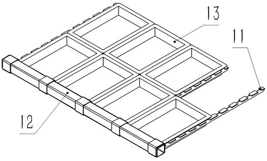
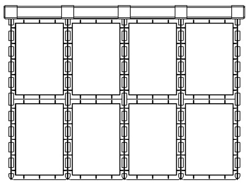
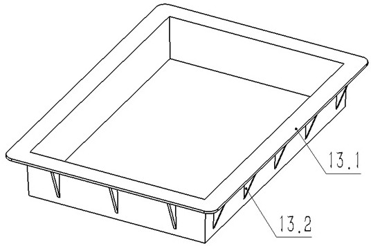
[0053] Embodiment 1, reference Figure 1 to Figure 4, a kind of concrete mold handling insert frame that one end of the insert plate is connected with the base frame, including the insert plate 11, the base frame 12, and the mold 13; the cross section of the insert plate 11 is T-shaped, and is composed of a vertical plate and a flat plate, and the flat plate has an opening, The opening corresponds to the ribs of the mould, and one end of the four parallel-placed inserts 11 is movably connected to the base frame 12, and the other end has a chamfer. There are 2 rows, 4 rows, and 8 molds 13 between the inserts 11. figure 1 One of the molds 13 is hidden to facilitate the observation of the part covered by it. There is a folded edge 13.1 on the upper edge of the mold 13. There is a rib 13.2 between the folded edge 13.1 and the side wall of the mold 13. The opening of the insert plate 11 leaves the rib 13.2 , when starting to use, adjust the distance between the plug-in boards 11, t...
Embodiment 2
[0054] Embodiment 2, refer to Figure 5 to Figure 8 , with reference to embodiment 1, a kind of concrete mold handling insert frame that the upper part of the insert plate is connected with the base frame, comprises insert plate 21, the base frame 22 that is connected as a whole two square tubes to form, mold 23, the section of insert plate 21 is I-shaped, the I-shaped lower plate has openings, and the openings correspond to the ribs of the mold 23 to avoid interference; the figure shows the state where the insert frame 21 is being inserted, the base frame 22 is connected to the hook of the crane, and the drive drives the insert frame to run Go to the front of the mold 23, adjust the height, the lower side of the inserting plate 21 is lower than the flange of the mold 23, the web of the inserting plate 21 is aligned between the two molds 23, and inserted forward until the end face of the inserting plate 21 is flush with the mold 23, At this moment, the opening of the inserting...
Embodiment 3
[0056] Embodiment 3, with reference to Embodiment 1, the embodiment of the rectangular cross-section inserting plate, as can be seen from the figure, adjacent mold flanges 13.1 are in contact with each other, and there is a space between the ribs 13.2 of adjacent molds, and this space can be Accommodate the flashboard of rectangular section, the flashboard inserts the folded edge 13.1 of mold 13, the benefit of rectangular section flashboard is needn't consider the interference of rib 13.2.
PUM
 Abstract
Description
Claims
Application Information
 - R&D Engineer
- R&D Manager
- IP Professional
- Industry Leading Data Capabilities
- Powerful AI technology
- Patent DNA Extraction
Browse by: Latest US Patents, China's latest patents, Technical Efficacy Thesaurus, Application Domain, Technology Topic, Popular Technical Reports.
© 2024 PatSnap. All rights reserved.Legal|Privacy policy|Modern Slavery Act Transparency Statement|Sitemap|About US| Contact US: help@patsnap.com