Printing and dyeing equipment

A technology of printing and dyeing equipment and printing and dyeing seats, which is applied in the direction of printing, printing machines, printing devices, etc., and can solve the problems of inability to realize the wind drying of pigments on clothing marks and the inability to organically combine them

Active Publication Date: 2020-11-27
常州京江源纺织有限公司
View PDF14 Cites 5 Cited by
  • Summary
  • Abstract
  • Description
  • Claims
  • Application Information

AI Technical Summary

Problems solved by technology

[0007] In order to solve the above technical problems, the present invention provides a printing and dyeing equipment to solve the problem that the purification devices of the existing devices are often driven by electricity, and cannot be linked to realize harmful gases during printing during the upper and lower printing processes. linkage absorption and filtration; moreover, the drying devices of the existing devices are often driven by electricity, and cannot be linked in the process of upper and lower printing to realize the wind drying of the pigment on the clothing logo; finally, the existing devices The problem that the purification structure and the drying structure cannot be organically combined with the fixed structure of the clothing logo

Method used


Image

  • Printing and dyeing equipment
  • Printing and dyeing equipment
  • Printing and dyeing equipment

Examples


Embodiment

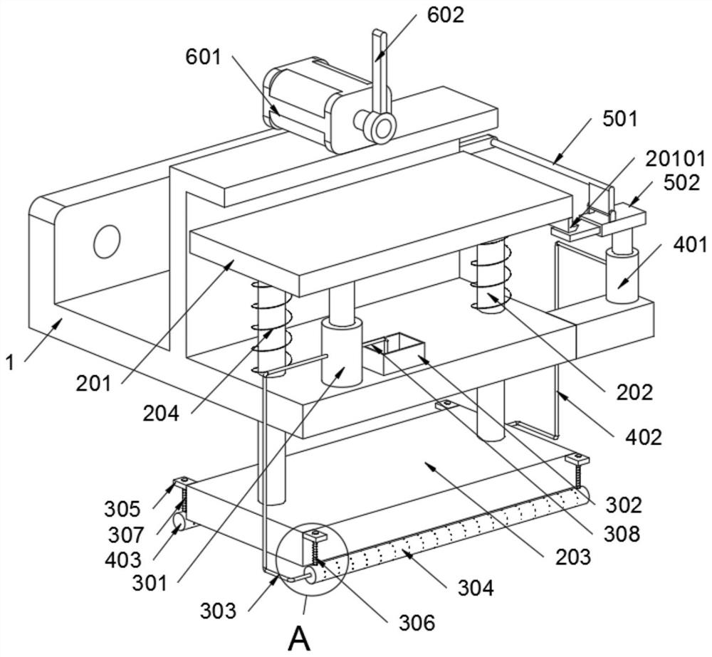
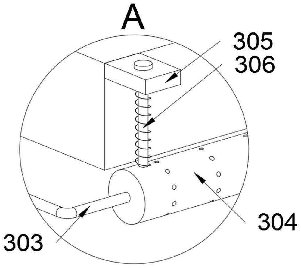
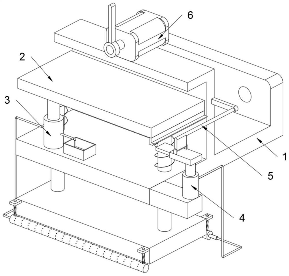
[0034] as attached figure 1 To attach Figure 8 Shown:

[0035] The present invention provides a printing and dyeing equipment, comprising a main body 1 and a rectangular plate 201; a printing and dyeing structure 2 is installed on the main body 1, and a purification structure 3 is installed on the main body 1, and a drying structure 4 is also installed on the main body 1 ; A toggle structure 5 is installed on the main body seat 1, and a driving structure 6 is installed on the main body seat 1; figure 1 with Image 6 , the rectangular plate 201 includes a toggle head 20101, and a toggle head 20101 is installed on the rectangular plate 201; the toggle structure 5 includes a connecting seat 501 and a telescopic box 502, the connecting seat 501 is fixedly connected to the main body seat 1 by bolts, and connected A telescopic box 502 is rotatably connected to the seat 501, and the bottom surface of the telescopic box 502 is in contact with the head end of the telescopic bottle ...


PUM


Abstract

The invention provides printing and dyeing equipment, and relates to the technical field of garment mark printing. The problems are solved that linkage absorption and filtration of harmful gas duringprinting cannot be achieved in a linkage manner in the up-and-down printing process, the wind power drying of pigment on a clothing mark cannot be achieved in a linkage manner in the up-and-down printing process, and a purification structure and a drying structure cannot be organically combined with a fixing structure of the clothing mark. The printing and dyeing equipment comprises a main body seat and a rectangular plate, wherein a printing and dyeing structure is mounted on the main body seat, a purification structure is mounted on the main body seat, and a drying structure is further mounted on the main body seat. As the outer wall of a spray head is slidably connected with two sliding rods B on the rear side, the two sliding rods B on the rear side are sleeved with two elastic piecesB, the two elastic pieces B jointly form an elastic reset structure of the spray head, the spray head is in an elastic contraction state when a printing and dyeing base conducts printing and dyeing, and normal printing and dyeing are not affected.

Description

technical field [0001] The invention belongs to the technical field of clothing logo printing, and more specifically relates to a printing and dyeing equipment. Background technique [0002] Clothes refer to the various styles of coverings made by human beings by using materials. At the same time, they are worn differently on different occasions. There are many styles. Clothes have become an indispensable thing today. It is often said in China Clothes have long been ranked first in basic necessities of life, and there are corresponding signs on each piece of clothing. [0003] For example, the application number: CN201822126093.9, the utility model discloses a printing and dyeing device for knitted children's clothing production marks, including printing and dyeing equipment, drying equipment and conveying equipment. Connecting rods are connected through, the upper and lower ends of the connecting rods are respectively provided with baffles and flapping plates, tension spri...

Claims


Application Information

Patent Timeline
Patent Type & Authority Applications(China)
IPC IPC(8): B41F1/04B41F1/26B41F1/56B41F23/04B41F35/00
CPCB41F1/04B41F1/26B41F1/56B41F23/04B41F35/00B41P2217/50B41P2235/27
Inventor 李许领
Owner 常州京江源纺织有限公司
Why Eureka
Try Eureka