Aircraft fuel tank inerting system and inerting method

A fuel tank and aircraft technology, applied in the field of aviation systems, can solve the problems of large compensation loss of aircraft, leakage of fuel vapor, membrane performance attenuation, etc., and achieve the effects of saving cold sources, reducing bleed air volume, and reducing compensation loss.

Inactive Publication Date: 2020-11-27
CHONGQING JIAOTONG UNIVERSITY
View PDF11 Cites 3 Cited by
  • Summary
  • Abstract
  • Description
  • Claims
  • Application Information

AI Technical Summary

Problems solved by technology

[0004] However, judging from the application status at home and abroad, there are still many problems in the use of airborne nitrogen inerting technology, such as the low efficiency of the separation membrane, which leads to large compensation losses of the aircraft, and the high demand pressure of the separation membrane inlet, which makes it unusable on many aircraft types. (such as helicopters), small membrane filaments and permeable pores are gradually blocked, and ozone in the gas source causes serious membrane performance attenuation, and when nitrogen-rich gas fills the fuel tank, fuel vapor leaks out and pollutes the environment, etc.

Method used


Image

  • Aircraft fuel tank inerting system and inerting method

Examples


Embodiment Construction

[0024] The present invention will be further described below in conjunction with the accompanying drawings and embodiments. It should be noted that in the description of the present invention, the terms "upper", "lower", "left", "right", "inner", "outer" etc. The indicated orientation or positional relationship is based on the orientation or positional relationship shown in the drawings, and is only for the convenience of describing the present invention and simplifying the description, rather than indicating or implying that the referred device or element must have a specific orientation or in a specific way construction and operation, therefore, should not be construed as limiting the invention. The terms "first", "second", "third", etc. are used for descriptive purposes only and should not be construed as indicating or implying relative importance.

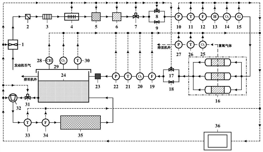
[0025] Such as figure 1 As shown, an aircraft fuel tank inerting system includes a fuel tank 24, the liquid outlet of the fu...


PUM


Abstract

The invention discloses an aircraft fuel tank inerting system which comprises a fuel tank, a liquid outlet of the fuel tank is connected with a second control valve through a pipeline, a downstream pipeline of the second control valve is sequentially connected with a fuel pump, a fifth temperature sensor, a third flow sensor and an electronic equipment cabin, and finally, the downstream pipeline of the second control valve is connected to a liquid inlet of the fuel tank through a pipeline. The fuel oil serves as a cold source, the temperature of the fuel oil rises while airborne equipment is cooled, and the vapor pressure of the fuel oil increases along with the rising of the temperature such that the vapor concentration of the fuel oil in the gas-phase space of the fuel tank is increased,and a non-combustible state is achieved. Meanwhile, fuel oil heating is combined with an aircraft-borne nitrogen-making inerting technology for preparing nitrogen-rich gas by using a hollow fiber membrane such that the inerting effect of the fuel tank is further ensured.

Description

technical field [0001] The invention relates to the technical field of aviation systems, in particular to an aircraft fuel tank inerting system and an inerting method. Background technique [0002] In the past 50 years, there have been 18 fuel tank explosion accidents of transport aircraft worldwide, killing a total of 542 people, which has become one of the main threats to civil aviation safety. In 1996, the combustible vapor of the TWA800 central wing fuel tank of Boeing 747 aircraft was ignited and caused an explosion, and all crew members were killed. This prompted the US Federal Aviation Administration to issue a series of amendments, advisory notices and airworthiness regulations, mandating that effective measures be taken to reduce ignition sources. and flammable vapor concentration to reduce the flammability of transport aircraft fuel tanks and increase the safety of fuel tanks. The Civil Aviation Administration of my country has also formulated similar aviation reg...

Claims


Application Information

Patent Timeline
Patent Type & Authority Applications(China)
IPC IPC(8): B64D37/32B64D37/34C01B21/04
CPCB64D37/32B64D37/34C01B21/0444C01B2210/0028C01B2210/0045
Inventor 邵垒毛虹霖吴滔黎涛彭思逸
Owner CHONGQING JIAOTONG UNIVERSITY
Why Eureka
Try Eureka