
Concentration device applied to heat source tower system

A technology of a concentration device and a heat source tower, which is applied in the field of heat source tower systems, can solve the problems of low concentration efficiency, separation and consumption of heating, and achieve the effect of high concentration efficiency

Pending Publication Date: 2020-11-27
武汉中电节能有限公司
View PDF5 Cites 0 Cited by
  • Summary
  • Abstract
  • Description
  • Claims
  • Application Information

AI Technical Summary

Problems solved by technology

Taking the concentration of circulating antifreeze in the heat source tower as an example, the existing heat source tower system usually uses evaporation to purify the dilute solution (or called antifreeze) in the system, but the evaporation method needs to consume extra heat and waste a lot of energy, and Evaporation purification efficiency is low
A small number of heat source tower systems use refrigeration to purify dilute solutions, but there is a problem that the size of the ice crystals is not compatible with the concentration efficiency; when the size of the ice crystals is small, it is difficult to separate the ice crystals from the concentrated solution; and in order to obtain larger ice crystals , requires a longer crystallization process, resulting in low concentration efficiency

Method used


Image

  • Concentration device applied to heat source tower system
  • Concentration device applied to heat source tower system
  • Concentration device applied to heat source tower system

Examples


Embodiment Construction

[0020] The present invention will be further described in detail below in conjunction with the accompanying drawings and specific embodiments.

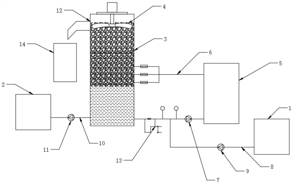
[0021] like figure 1 The shown concentrating device used in the heat source tower system includes an ice making system, a dilute solution pool 1, a concentrated solution pool 2, a concentrating bucket 3 and a stirring device 4; the ice making system includes an ice making device 5, a circulation pipeline 6 and a circulation The pump 7 ; the ice making device 5 communicates with the concentrator barrel 3 through the circulation pipeline 6 , and the circulation pump 7 is arranged on the circulation pipeline 6 .

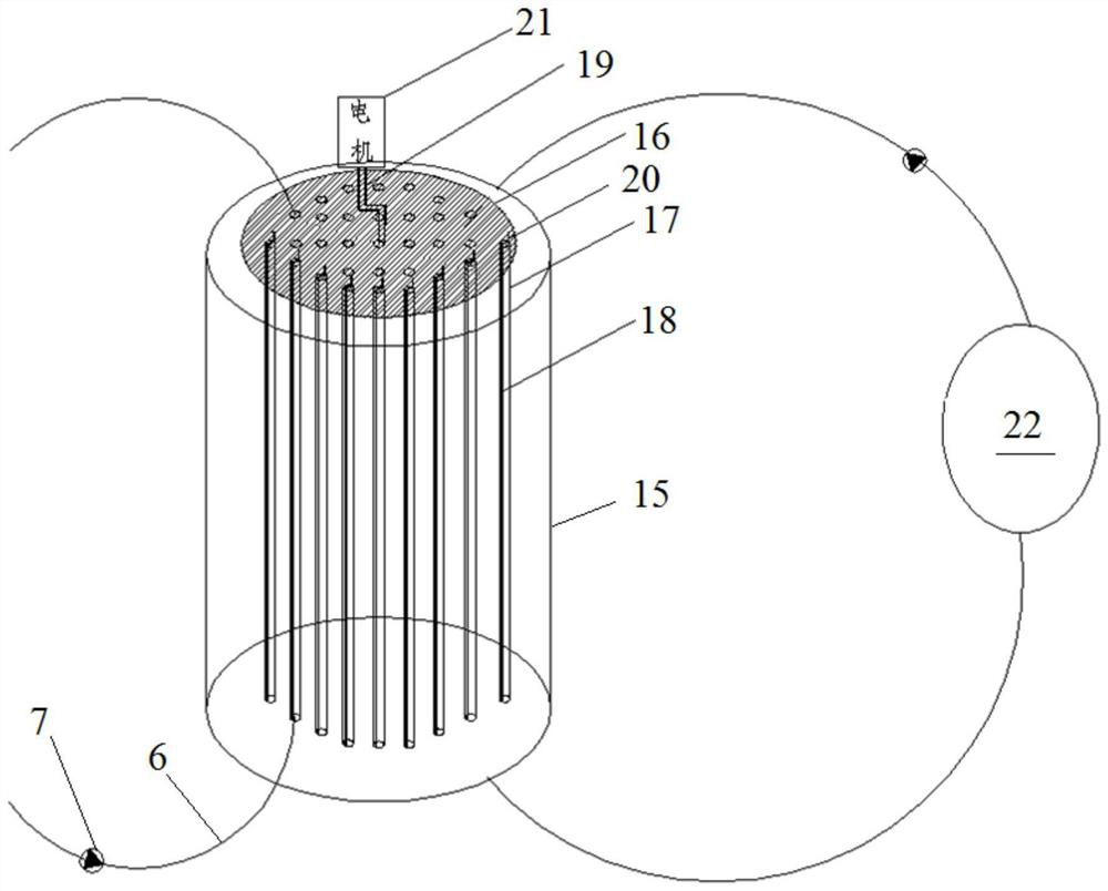
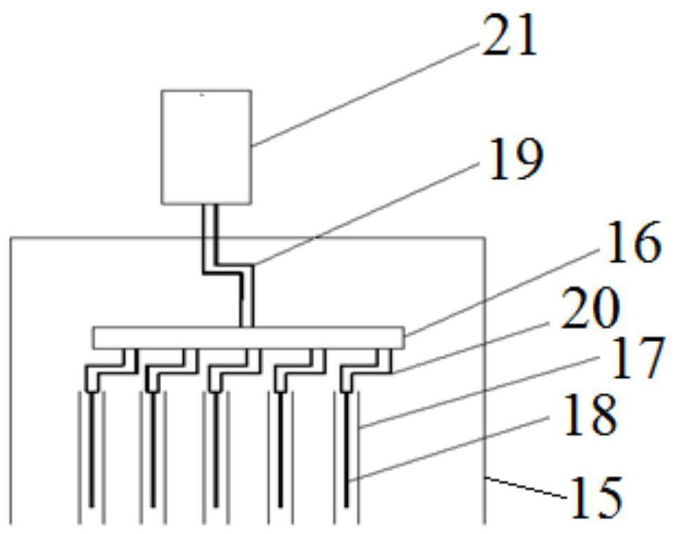
[0022] The ice making device 5 can adopt existing equipment, wherein the circulating pipeline 6 preferably includes at least one section of parallel copper tubes, and the multiple copper tubes are in full contact with the refrigerant in the refrigeration device to improve the dilute solution flowing through the copper tubes. T...


PUM


Abstract

The invention discloses a concentration device applied to a heat source tower system. The concentration device comprises an ice making system, a dilute solution pool, a concentrated solution pool, a concentration barrel and a stirring device, wherein the ice making system comprises an ice making device, a circulating pipeline and a circulating pump; the dilute solution pool communicates with the circulating pipeline through a liquid inlet pipeline; the concentrated solution pool communicates with the concentration barrel through a liquid outlet pipeline; the stirring device is arranged at theupper end of the concentrating barrel; the stirring device comprises a stirring motor and stirring blades; and an ice outlet is formed in a position, corresponding to the stirring blades, of the sidewall of the concentration barrel. The concentration device has the beneficial effects that a dilute solution in the concentration barrel is crystallized to form an ice-water mixture through the ice making system, ice blocks floating above can be rapidly separated from the concentrated solution through the stirring device, separation and concentration can be synchronously carried out, concentrationof the dilute solution is not affected in the ice block separation process, and concentration efficiency is high.

Description

technical field [0001] The invention relates to the technical field of heat source tower systems, in particular to a concentration device applied to heat source tower systems. Background technique [0002] Concentration of aqueous solutions is a common procedure in many industries. The techniques widely used for the concentration of aqueous solutions are evaporation and freezing. The equipment required for the evaporation method is simple, but the effective evaporation process must be carried out under high temperature boiling conditions, which may lead to the loss and / or destruction of certain volatile or heat-sensitive substances in the solution. Freezing is the process of concentrating an aqueous solution by causing the water in the solution to crystallize into ice at a temperature below the freezing point of the solution. Taking the concentration of circulating antifreeze in the heat source tower as an example, the existing heat source tower system usually uses evapora...

Claims


Application Information

Patent Timeline
Patent Type & Authority Applications(China)
IPC IPC(8): C02F1/22B01D9/04
CPCC02F1/22B01D9/04B01D9/0013
Inventor 钟凡叶洵商凯李金涛
Owner 武汉中电节能有限公司
Learn More