Heat dissipation system based on pump-driven capillary phase change loop

A heat dissipation system and capillary technology, applied in the direction of instruments, electrical digital data processing, digital data processing components, etc., can solve the problems of small transmission distance of loop heat pipe and capillary pump circuit, difficult to start, etc., to increase the heat transmission distance, The effect of avoiding start failures and improving the ability to transfer heat loads

Pending Publication Date: 2020-11-27
包文隆 +1
View PDF0 Cites 2 Cited by
  • Summary
  • Abstract
  • Description
  • Claims
  • Application Information

AI Technical Summary

Problems solved by technology

For this reason, the object of the present invention is to propose a heat dissipation system based on a pump-driven capillary phase change circuit, which combines active heat dissipation technology and passive heat dissipation technology, and uses the phase change latent heat of the working fluid to improve heat transfer capacity and meet high heat flux density It has high heat transfer efficiency, which not only increases the power of power electronic devices, but also greatly improves the working efficiency of electronic devices, and solves the shortcomings of loop heat pipes and capillary pump loops such as small transmission distance and difficulty in starting. The heat dissipation of electronic devices is of great significance. It is an improvement and extension of loop heat pipe technology, and it is suitable for the heat dissipation of electronic devices with different heat flux densities.

Method used


Image

  • Heat dissipation system based on pump-driven capillary phase change loop
  • Heat dissipation system based on pump-driven capillary phase change loop
  • Heat dissipation system based on pump-driven capillary phase change loop

Examples


Embodiment Construction

[0080] The preferred embodiments of the present invention will be described below in conjunction with the accompanying drawings. It should be understood that the preferred embodiments described here are only used to illustrate and explain the present invention, and are not intended to limit the present invention.

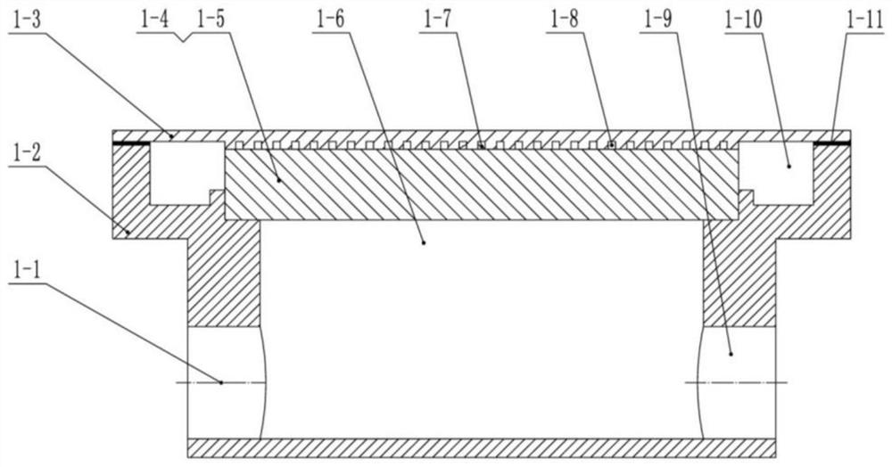
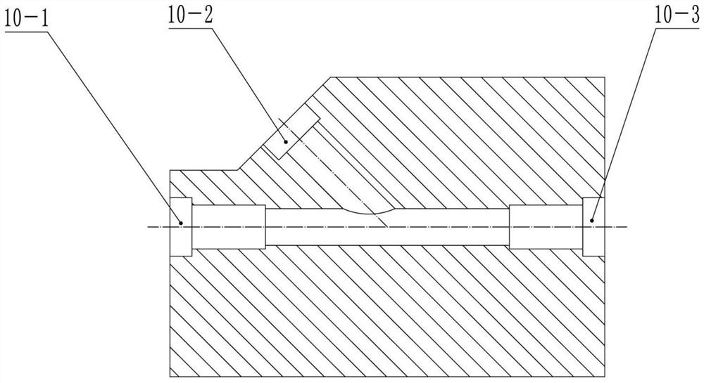
[0081] Refer below Figure 1 to Figure 5 A heat dissipation system based on a pump-driven capillary phase change circuit proposed by an embodiment of the present invention will be described.

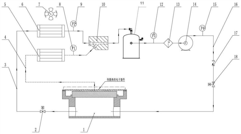
[0082] figure 1 It is a schematic diagram of a heat dissipation system based on a pump-driven capillary phase change circuit in an embodiment of the present invention; as figure 1 As shown, the embodiment of the present invention proposes a heat dissipation system based on a pump-driven capillary phase change circuit, including: a first liquid pipeline 16, a second liquid pipeline 3, a steam pipeline 4, an ejector 10, and an evaporator 1; where,

[0083] The first end of th...


PUM


Abstract

The invention discloses a heat dissipation system based on a pump drive capillary phase change loop. The heat dissipation system comprises a first liquid pipeline, a second liquid pipeline, a steam pipeline, an ejector and an evaporator. The first end of the second liquid pipeline is communicated with the first end of the first liquid pipeline through the ejector, and the second end of the secondliquid pipeline is communicated with the second end of the first liquid pipeline through the evaporator; the first end of the steam pipeline is communicated with the first end of the first liquid pipeline through an ejector; the second end of the steam pipeline is communicated with the second end of the first liquid pipeline through the evaporator; an active heat dissipation technology and a passive heat dissipation technology are combined; the heat exchange capability is improved by utilizing phase change latent heat of the working medium; the heat dissipation system meets the heat dissipation requirement of high heat flow density, has high heat transfer efficiency, improves the power of electric power and electronic devices, improves the working efficiency of the electric power and the electronic devices. The defects that a loop heat pipe and a capillary pump loop are small in transmission distance, difficult to start and the like are overcome, and the heat dissipation system adaptsto heat dissipation of the electronic devices with different heat flow densities.

Description

technical field [0001] The invention relates to the technical field of thermal control, in particular to a heat dissipation system based on a pump-driven capillary phase change circuit. Background technique [0002] At present, the traditional cooling methods mainly include natural convection cooling, forced convection cooling, liquid cooling, and refrigeration system cooling. Natural convection cooling uses natural air convection and radiation to dissipate heat, with limited cooling capacity, and is mainly used for cooling electronic devices with small heat generation. Forced convection cooling removes heat from electronics by forcing air through it with a fan. Natural convection and forced convection cooling mainly increase the heat transfer coefficient by increasing the heat dissipation area and increasing the turbulence. The liquid cooling and heat dissipation method uses power equipment such as pumps to drive water, oil and other coolants to circulate in the cooling s...

Claims


Application Information

Patent Timeline
Patent Type & Authority Applications(China)
IPC IPC(8): G06F1/20
CPCG06F1/20G06F1/206G06F2200/201Y02D10/00
Inventor 侯世红包文隆
Owner 包文隆
Why Eureka
Try Eureka