Baseband non-stationary digital signal denoising method and system and storage medium thereof

A digital signal, non-stationary technology, used in electrical digital data processing, pattern recognition in signals, complex mathematical operations, etc., can solve the problems of slow calculation speed and high computational complexity, reduce hardware costs, and reduce computational complexity. , the effect of fast operation

Pending Publication Date: 2020-11-27
NANJING COLLEGE OF INFORMATION TECH
View PDF0 Cites 0 Cited by
  • Summary
  • Abstract
  • Description
  • Claims
  • Application Information

AI Technical Summary

Problems solved by technology

[0005] Aiming at the problems of high computational complexity and slow computational speed in denoising in the prior art, the present invention proposes a baseband non-stationary digital signal denoising method, system and storage medium, using an improved frequency domain filter To achieve a good denoising effect, at the same time reduce the complexity of denoising calculations and improve the calculation speed

Method used


Image

  • Baseband non-stationary digital signal denoising method and system and storage medium thereof
  • Baseband non-stationary digital signal denoising method and system and storage medium thereof
  • Baseband non-stationary digital signal denoising method and system and storage medium thereof

Examples


Embodiment 1

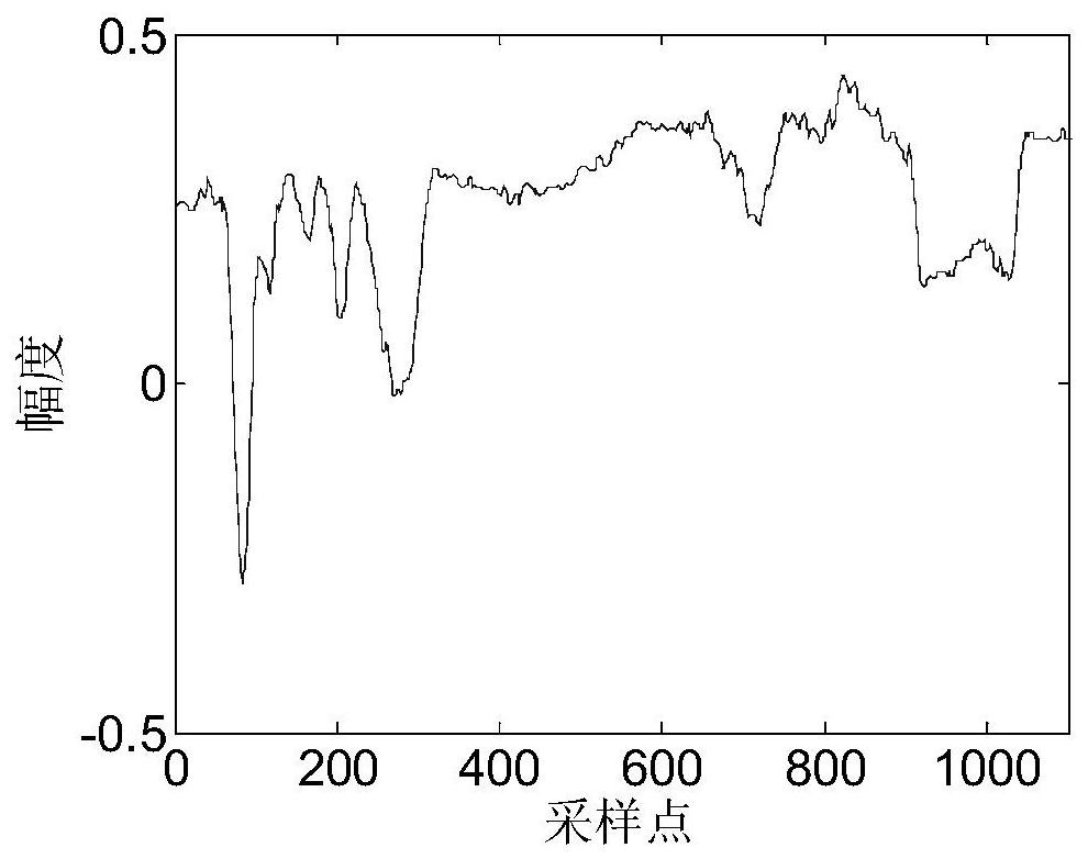
[0052] A 1100-point baseband non-stationary digital signal is simulated as the original signal, such as image 3 As shown, after adding Gaussian white noise to the signal, it is formed as Figure 4 The signal-to-noise ratio shown is 3dB for the signal to be processed, from Figure 4 It can be seen that due to the strong noise, the details of the waveform are completely unrecognizable.

[0053] Using Serbes wavelet denoising method to process Figure 4 The signal shown, the denoising result is as follows Figure 5 As shown, will Figure 5 and image 3 It can be seen from the comparison that the wavelet denoising method can reflect the overall trend of the original signal on the whole, and the waveform after wavelet denoising is relatively smooth. This is because the wavelet denoising method filters out more high-frequency components of the signal, but , the wavelet denoising method is Figure 5 There is an overshoot phenomenon at the middle circle.

[0054] Utilize the m...

Embodiment 2

[0057] In order to further check the processing effect of the inventive method on the baseband non-stationary digital signal, a 1100-point baseband non-stationary digital signal is simulated as the original signal, such as Figure 7 As shown, after adding Gaussian white noise to the signal, it is formed as Figure 8 The signal-to-noise ratio shown is 3dB for the signal to be processed, Figure 8 The details of the medium waveform are also completely unrecognizable.

[0058] Using Serbes wavelet denoising method to process Figure 8 The signal shown, the denoising result is as follows Figure 9 As shown, will Figure 9 and Figure 7 It can be seen from the comparison that the wavelet denoising method can basically reflect the overall trend of the original signal. However, in Figure 9 In the area indicated by the middle circle, the details of the denoising results of the wavelet denoising method are seriously lost.

[0059] Utilize the method of the present invention to p...


PUM


Abstract

The invention discloses a baseband non-stationary digital signal denoising method, a baseband non-stationary digital signal denoising system and a storage medium thereof, and aims to solve the technical problem of relatively high calculation complexity of a denoising method in the prior art. The method comprises the following steps: designing a frequency domain filter for the characteristics of abaseband non-stationary digital signal; performing fast Fourier transform on the to-be-processed baseband non-stationary digital signal to obtain a frequency spectrum of the to-be-processed signal; multiplying the frequency spectrum of the signal to be processed by a frequency domain filter, and carrying out frequency domain filtering; and performing inverse fast Fourier transform on the frequencydomain filtering result to obtain a denoised output signal. The method has a good denoising effect, and compared with the prior art, the method is low in calculation complexity and higher in calculation speed.

Description

technical field [0001] The invention relates to a baseband non-stationary digital signal denoising method, system and storage medium thereof, belonging to the technical field of digital signal processing. Background technique [0002] Signals are divided into two types: analog signals and digital signals. Since digital signals are suitable for large-scale digital integrated circuit operations, digital signals are currently the most widely used signal form. Digital signals are divided into baseband digital signals and frequency band digital signals. Frequency band digital signals can be converted into baseband digital signals by removing the carrier. Therefore, the processing method of baseband digital signals is the most basic problem in signal processing research. [0003] Baseband digital signals can be divided into two types: stationary and non-stationary. In various fields of signal processing, baseband non-stationary digital signals are encountered in most cases, such a...

Claims


Application Information

Patent Timeline
Patent Type & Authority Applications(China)
IPC IPC(8): G06K9/00G06F17/14
CPCG06F17/142G06F2218/04
Inventor 罗文茂姜敏敏顾艳华陈雪娇
Owner NANJING COLLEGE OF INFORMATION TECH
Why Eureka
Try Eureka