
Wire rod cooling device

A cooling device and wire technology, applied in metal material coating process, coating, hot dip plating process, etc., can solve the problems of increasing operating costs, affecting the speed of the welding strip, affecting the hot dip coating, etc., and achieving high cooling Efficiency, the effect of improving the wire speed

Pending Publication Date: 2020-12-01
昆山奥特莱机电科技有限公司
View PDF4 Cites 0 Cited by
  • Summary
  • Abstract
  • Description
  • Claims
  • Application Information

AI Technical Summary

Problems solved by technology

However, the liquid flow formed by the cooling liquid and the air flow generated by the inert gas in the protective tube act on the welding strip, which still affects the strip speed of the welding strip. If the strip speed is high, the welding strip will vibrate violently, thus affecting the hot dip coating of the previous sequence. cover
In addition, during the operation of the device, it is still necessary to consume inert gas and increase the operating cost

Method used


Image

  • Wire rod cooling device
  • Wire rod cooling device
  • Wire rod cooling device

Examples


Embodiment Construction

[0047] The technical solutions of the present invention will be clearly and completely described below in conjunction with the accompanying drawings. Apparently, the described embodiments are some of the embodiments of the present invention, but not all of them. Based on the embodiments of the present invention, all other embodiments obtained by persons of ordinary skill in the art without making creative efforts belong to the protection scope of the present invention.

[0048] In the description of the present invention, it should be noted that the terms "center", "upper", "lower", "left", "right", "vertical", "horizontal", "inner", "outer" etc. The indicated orientation or positional relationship is based on the orientation or positional relationship shown in the drawings, and is only for the convenience of describing the present invention and simplifying the description, rather than indicating or implying that the referred device or element must have a specific orientation, ...


PUM


Abstract

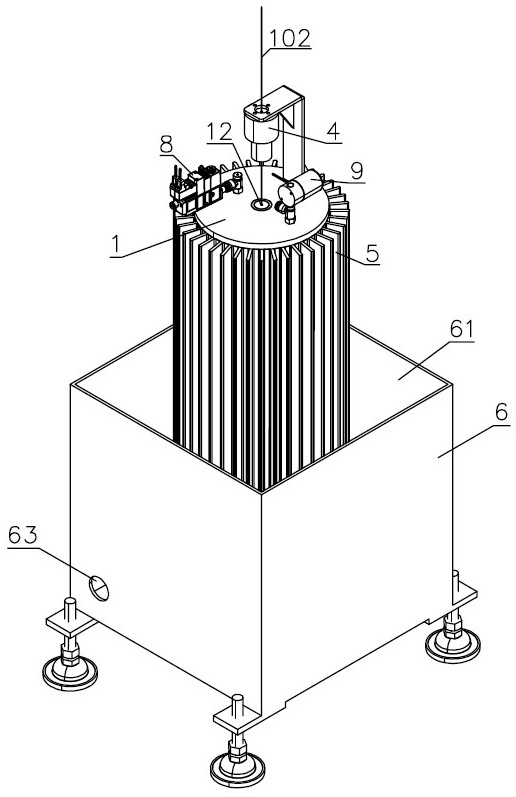
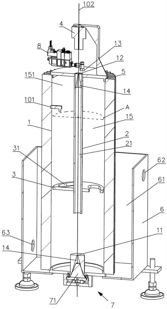
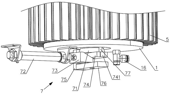
The invention relates to a wire rod cooling device. The wire rod cooling device comprises a cooling cylinder and an inner pipe, wherein the cooling cylinder is provided with an inner cavity, the innercavity is used for loading cooling liquid, and a wire inlet and a wire outlet are formed in the lower end and the upper end of the cooling cylinder correspondingly; and the periphery of the upper endof the inner pipe is connected to the periphery of the wire outlet in a sealed mode, a wire passing channel is formed in the inner pipe, and the lower end of the inner pipe extends towards the wire inlet; and an extraction opening is further formed in the cooling cylinder and communicates an the inner cavity between the outer wall of the inner pipe and the inner wall of the cooling cylinder. Thebelt speed of a wire rod can be increased.

Description

technical field [0001] The invention relates to a wire rod cooling device, which is used for cooling photovoltaic soldering strips after being tinned, and can also be used for cooling other wire rods. Background technique [0002] Photovoltaic welding ribbon is tinned copper strip, which is used in the connection of photovoltaic module cells and is an important raw material in the welding process of photovoltaic modules. [0003] When the photovoltaic ribbon is tinned, it has to pass through a tin melting furnace at 230 degrees Celsius. After the ribbon passes through the tin furnace, the temperature can reach more than 100 degrees Celsius, and it needs to be cooled before it can be wound. And the cooling treatment can make the tin layer more uniform and adhere firmly. In reality, cold air cooling and liquid nitrogen cooling are usually used. [0004] Among them, cold air cooling usually uses inert gas and air-conditioning refrigeration, which has the disadvantages of high...

Claims


Application Information

Patent Timeline
Patent Type & Authority Applications(China)
IPC IPC(8): C23C2/08C23C2/26C23C2/38C23C2/40
CPCC23C2/003C23C2/08C23C2/26C23C2/38C23C2/40
Inventor 刘勇刘辉
Owner 昆山奥特莱机电科技有限公司
Learn More