A kind of anti-dust equipment for construction site

A construction site, anti-dust technology, applied in separation methods, dispersed particle separation, chemical instruments and methods, etc., can solve problems such as the inability to actively reduce air dust content, achieve good dust removal effect and reduce power consumption.

Active Publication Date: 2021-12-03
嘉兴尚坤科技有限公司
View PDF5 Cites 0 Cited by
  • Summary
  • Abstract
  • Description
  • Claims
  • Application Information

AI Technical Summary

Problems solved by technology

[0004] The purpose of the present invention is to solve the shortcomings of the prior art that the protective plate can only prevent the dust from spreading and cannot actively reduce the dust content in the air, and proposes a kind of anti-dust equipment for construction sites

Method used


Image

  • A kind of anti-dust equipment for construction site
  • A kind of anti-dust equipment for construction site
  • A kind of anti-dust equipment for construction site

Examples


Embodiment 1

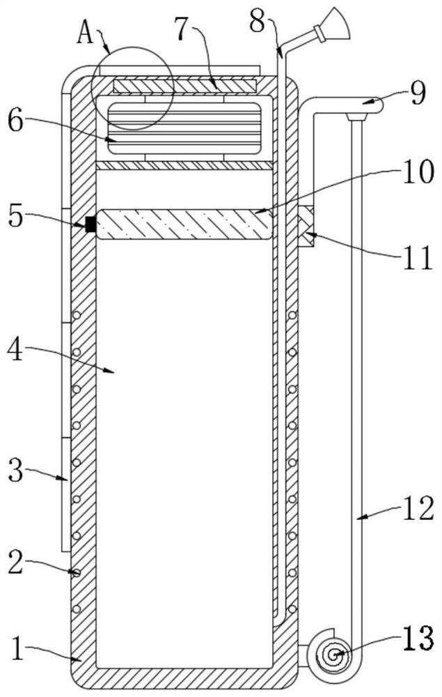
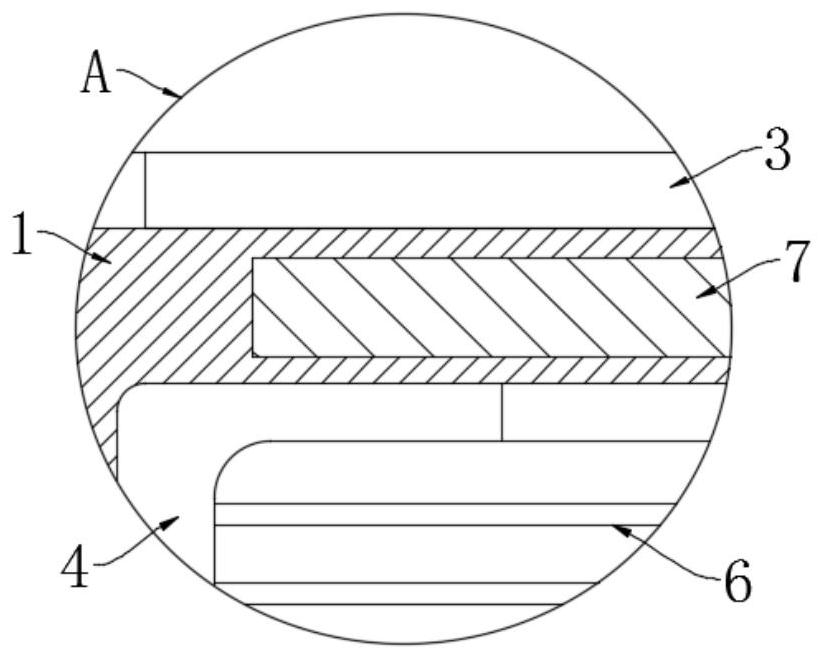
[0024] refer to Figure 1-2 , a kind of anti-dust equipment for a construction site, comprising a fixed plate 1, a hollow groove 4 is opened in the fixed plate 1, an electromagnetic coil 6 is fixedly installed on the inner top wall of the hollow groove 4, and a permanent magnet is arranged for sealing and sliding in the hollow groove 4 10. A plurality of photovoltaic panels 3 are arranged in an array on the outer wall of the fixed plate 1. The wire group 2, the touch panel 5 and the circuit board 7 are fixed inside the side wall of the fixed plate 1, and the circuit board 7 is connected with the wires. The group 2 is respectively located above and below the electromagnetic coil 6, and the touch panel 5 is located between the wire group 2 and the electromagnetic coil 6;

[0025] A storage battery (not shown) electrically connected to the photovoltaic panel 3, the touch panel 5, the electromagnetic coil 6, and the circuit board 7 is also arranged in the fixed plate 1, and the wi...

Embodiment 2

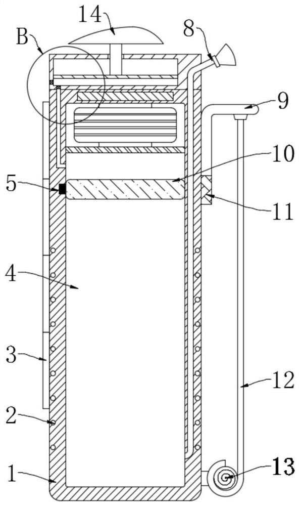
[0038] refer to Figure 2-4 , the present embodiment differs from Embodiment 1 in that: the upper end of the fixed plate 1 is fixedly provided with a sealing box 15, and a sliding plate 16 is arranged for sealing and sliding in the sealing box 15, and a straight rod is welded on the sliding plate 16, and the upper end of the straight rod Through the top of the sealing box 15 and connected with the wing plate 14, the side wall of the sealing box 15 is provided with an air inlet 17 and an exhaust port 19, and the air inlet 17 is connected with the hollow groove 4 through an elbow 18, and the elbow The junction of the tube 18 and the hollow slot 4 is located above the permanent magnet 10 .

[0039] In this embodiment, a one-way valve is installed in the air inlet 17 and the exhaust port 19. Under the action of the one-way valve, the air can only flow along the hollow groove 4-intake port 17-sealed box 15-exhaust port 19 direction of movement.

[0040] When the equipment is in u...


PUM


Abstract

The invention discloses a dust prevention device for a construction site, which comprises a fixed plate, a hollow groove is opened in the fixed plate, an electromagnetic coil is fixedly installed on the inner top wall of the hollow groove, and a sealing slide is arranged in the hollow groove. There are permanent magnets, and a plurality of photovoltaic panels are arranged in an array on the outer wall of the fixed plate, and a wire group, a touch panel and a circuit board are fixed in the side wall of the fixed board, and the circuit board and the wire group They are respectively located above and below the electromagnetic coil, the touch panel is located between the wire group and the electromagnetic coil, a lightweight plate is slidably arranged on the outer wall of the fixed plate, and the lower end of the light plate is fixedly clamped with a As for the adsorption strip, the upper end of the light plate is fixedly bonded with a dust-proof net, and the lower part of the fixed plate is fixedly equipped with a scraper. The invention can not only automatically flatten and roll up the dust-proof net to capture the dust in the air, but also intermittently spray water mist to reduce the dust content in the air.

Description

technical field [0001] The invention relates to the technical field of building construction, in particular to a dust prevention device for a construction site. Background technique [0002] During construction on the construction site, a large amount of building materials such as cement, sand, bricks, and concrete are required, so dust is extremely easy to appear on the construction site. In order to prevent the dust from spreading to the surrounding environment, protective panels are often used to enclose the construction site. [0003] The general protective plate is made of plastic, alloy and other materials, which can only prevent the dust from spreading to the outside world, and cannot actively reduce the dust content in the air on the construction site. It also needs a fog cannon vehicle to cooperate with dust suppression, and the fog cannon vehicle is large in size. It consumes a lot of power, requires additional personnel to control, and is not suitable for small-sc...

Claims


Application Information

Patent Timeline
Patent Type & Authority Patents(China)
IPC IPC(8): E04G21/00B01D50/00
CPCE04G21/00B01D50/60
Inventor 王梓权
Owner 嘉兴尚坤科技有限公司
Why Eureka
Try Eureka