
Plunger pump with good heat dissipation effect

A heat dissipation effect and plunger pump technology, which is applied to parts of pumping devices for elastic fluids, pump elements, variable displacement pump parts, etc., can solve the problem of damage to plunger pumps, difficult removal, oil seals and oil viewing windows Damage and other problems, to achieve high heat dissipation efficiency, improve heat dissipation effect, and improve heat dissipation ability

Active Publication Date: 2020-12-01
芜湖西南机械有限公司
View PDF4 Cites 2 Cited by
  • Summary
  • Abstract
  • Description
  • Claims
  • Application Information

AI Technical Summary

Problems solved by technology

[0003] When the plunger pump is working, the crankshaft rotates at high speed in the plunger pump synchronously with the supporting power mechanism, and the plunger reciprocates at high speed through the connecting rod mechanism, which will generate a lot of heat during this period. The existing technology uses aluminum Alloy material is used as the material of the crankcase and many heat sinks are designed on the crankcase to eliminate these effects, but sometimes the plunger pump is prone to heat up to over 100 degrees Celsius, causing damage to the oil seal and oil viewing window, and leakage of lubricating oil, resulting in Piston pumps are sometimes damaged, and the cooling fins on the crankcase have been used for a long time in the plunger pumps, and dirt is easy to accumulate, which is difficult to remove, resulting in limited heat dissipation

Method used


Image

  • Plunger pump with good heat dissipation effect
  • Plunger pump with good heat dissipation effect
  • Plunger pump with good heat dissipation effect

Examples


Embodiment Construction

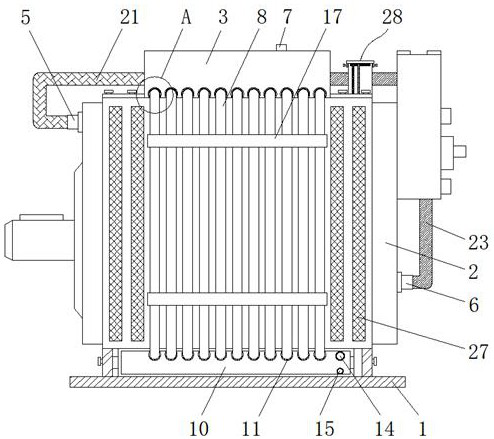
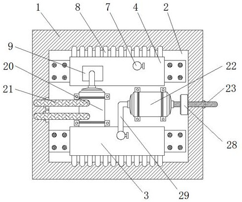
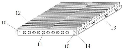
[0028] In order to deepen the understanding of the present invention, the present invention will be further described below in conjunction with the examples, which are only used to explain the present invention, and do not constitute a limitation to the protection scope of the present invention.

[0029] according to figure 1 , 2 , 3, 4, 5, and 6, this embodiment provides a plunger pump with good heat dissipation effect, including a pump body base 1, a plunger pump body 2, a cooling water tank 3, a buffer water tank 4, an inlet water cooling and heat dissipation Components and water outlet cooling and heat dissipation components, the pump body base 1 is provided with a plunger pump body 2, one side of the plunger pump body 2 is provided with a water inlet 5, and the other side of the plunger pump body 2 is provided with There is a water outlet 6, a cooling water tank 3 is provided above the plunger pump body 2, a buffer water tank 4 is provided on one side of the cooling wate...


PUM


Abstract

The invention discloses a plunger pump with a good heat dissipation effect. The plunger pump comprises a pump body base, a plunger pump body, a cooling water tank, a buffer water tank, a water inlet cooling heat dissipation assembly and a water outlet cooling heat dissipation assembly. The cooling water tank is arranged above the plunger pump body, the buffer water tank is arranged on one side ofthe cooling water tank, cooling pipes are arranged on the side wall of the cooling water tank, the water pump is arranged in the buffer water tank, the water outlet end of the water pump penetrates through the buffer water tank and then is provided with the water inlet cooling heat dissipation assembly, and the water outlet cooling heat dissipation assembly is arranged on one side of the water inlet cooling heat dissipation assembly. According to the plunger pump with the good heat dissipation effect, by arranging the cooling water tank, the buffer water tank and the water inlet cooling heat dissipation assembly, firstly cooling water can be conveyed through the cooling pipes to dissipate heat of the surface of the plunger pump body, the multiple sets of cooling pipes are tightly attachedto the surface of the plunger pump body, the heat dissipation efficiency is high, then the cooling pipes are used for conveying the cooling water to dissipate heat the interior of the plunger pump body, and the heat dissipation effect can be effectively improved.

Description

technical field [0001] The invention relates to the field of plunger pumps, in particular to a plunger pump with good heat dissipation effect. Background technique [0002] The plunger pump is a reciprocating motion driven by the eccentric rotation of the crankshaft. Its suction and discharge are all one-way valves. The one-way valve and the water seal form a closed space. When the plunger is pulled outward, the atmospheric pressure in the working chamber decreases, the outlet valve closes, and the pressure in the working chamber is lower than the atmospheric pressure, which means that the inlet valve opens and the liquid enters the working chamber; when the plunger is pushed inward, the pressure in the working chamber is greater than the external atmospheric pressure, which means The inlet valve is closed, the outlet valve is opened, and the liquid is discharged. In this way, the plunger pump completes a complete single working cycle through one revolution of the crankshaft...

Claims


Application Information

Patent Timeline
Patent Type & Authority Applications(China)
IPC IPC(8): F04B53/08F04B53/00F04B53/16
CPCF04B53/08F04B53/00F04B53/16
Inventor 蒋润
Owner 芜湖西南机械有限公司
Learn More