Vibration monitoring system and method
A technology of monitoring system and shock sensor, which is applied in the direction of instruments, measuring devices, using wave/particle radiation, etc., can solve problems affecting communication services, connection boxes falling off, swinging, etc.
- Summary
- Abstract
- Description
- Claims
- Application Information
AI Technical Summary
Problems solved by technology
Method used
Image

Examples
Embodiment 1
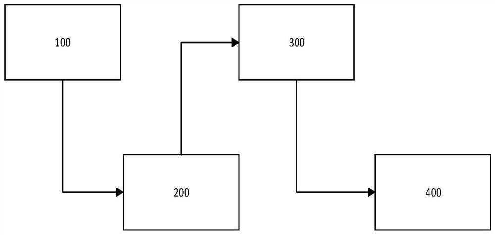
[0049] Such as figure 1 As shown, according to a specific embodiment of the present invention, in a first aspect, the present invention provides a vibration monitoring system, comprising:
[0050] The fiber grating type shock sensor 100, the optical modem 200, the signal processing device 300 and the display terminal 400;
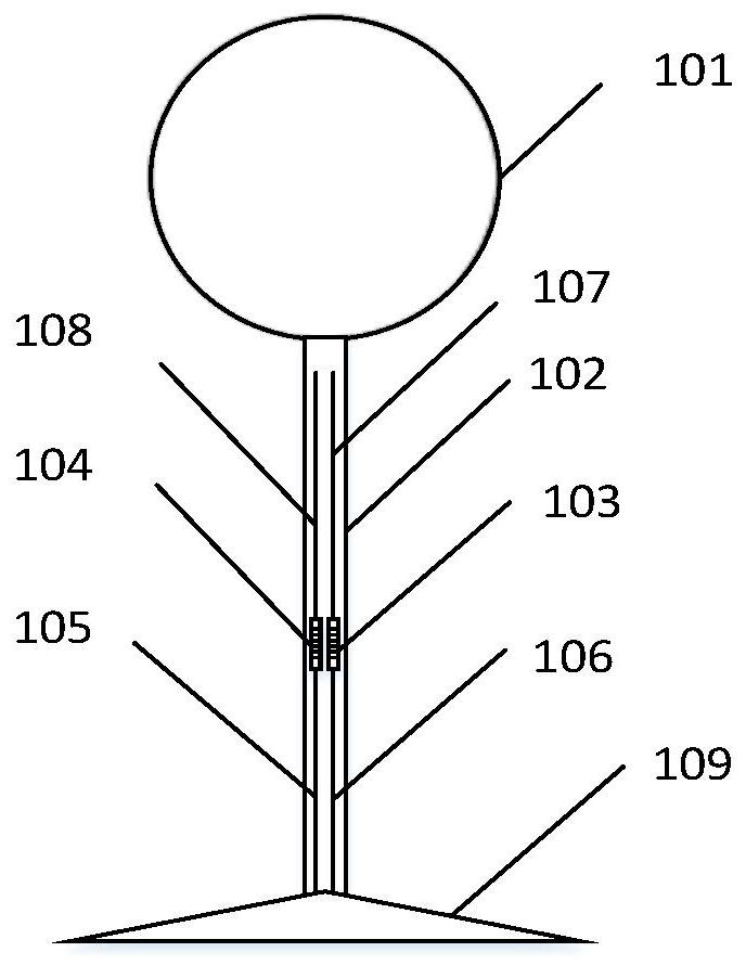
[0051] Such as figure 2 As shown, the fiber grating type shock sensor 100 includes: a weight ball 101, a cantilever beam 102 and a base 109; the cantilever beam 102 is connected to the weight ball 101 at one end and connected to the base 109 at the other end, and the base 109 is placed On the horizontal plane, it is used to support the cantilever beam 102 and the weight ball 101. The weight ball 101 is made of shot put quality rubber or stainless steel.
[0052] Among them, the material of the weight ball is not limited to the above two types, and can be flexibly set according to the application in different objects to be tested. For example, according ...
Embodiment 2
[0072] Such as figure 1 As shown, according to a specific embodiment of the present invention, the present invention provides another vibration monitoring system, comprising:
[0073] The fiber grating type shock sensor 100, the optical modem 200, the signal processing device 300 and the display terminal 400;
[0074] Such as figure 2 As shown, the fiber grating type shock sensor 100 includes: a weight ball 101, a cantilever beam 102 and a base 109; the cantilever beam 102 is connected to the weight ball 101 at one end and connected to the base 109 at the other end, and the base 109 is placed On the horizontal plane, it is used to support the cantilever beam 102 and the weight ball 101. The weight ball 101 is made of shot put quality rubber or stainless steel.
[0075] Among them, the material of the weight ball is not limited to the above two types, and can be flexibly set according to the application in different objects to be tested. For example, according to different ...
Embodiment 3
[0096] Such as Figure 5 As shown, according to a specific embodiment of the present invention, in a second aspect, the present invention provides a vibration monitoring method, comprising:
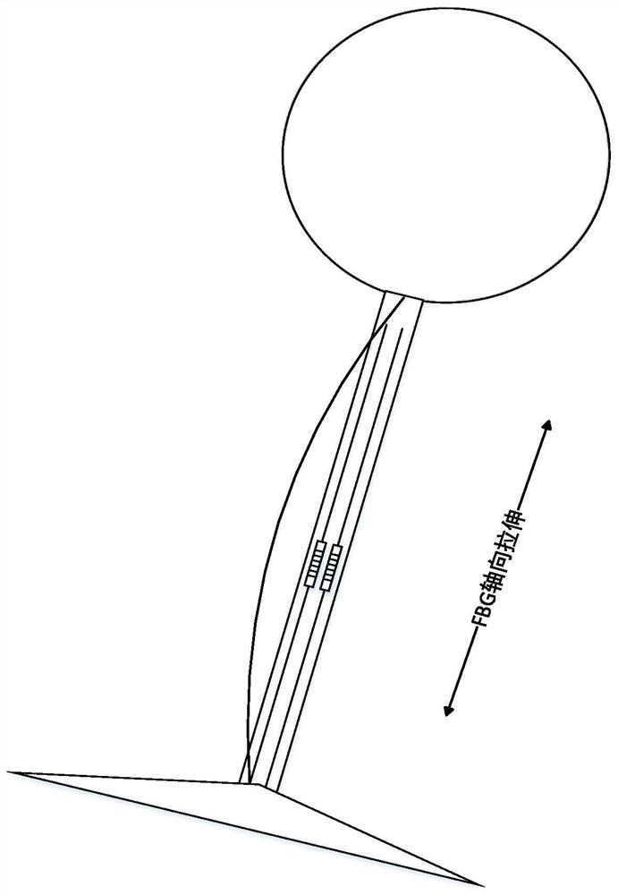
[0097] Step S100: place the fiber grating type shock sensor 100 on a horizontal plane, the fiber grating type shock sensor 100 senses the vibration, swing and / or tilt caused by changes in external conditions, and generates a light sensing signal, and transmits the light sensing signal to to the optical modem 200;
[0098] Wherein, the cantilever beam 102 includes two fiber gratings 103 and 104, and when the temperature is constant, it can be clearly seen that the wavelength variation is directly proportional to the pressure variation.
[0099] Δλ 1 =K T1 ΔT+K ε1 ε (1)
[0100] Δλ 2 =K T2 ΔT+K ε2 ε (2)
[0101] (2)-(1)
[0102] Δλ=Δλ B2 -Δλ B1 = 2K ε2 ε (3)
[0103] Among them, Δλ 1 is the wavelength offset of fiber Bragg grating FBG1, Δλ 2 is the fiber Bragg grating FBG2 w...
PUM
 Abstract
Description
Claims
Application Information
 - R&D
- Intellectual Property
- Life Sciences
- Materials
- Tech Scout
- Unparalleled Data Quality
- Higher Quality Content
- 60% Fewer Hallucinations
Browse by: Latest US Patents, China's latest patents, Technical Efficacy Thesaurus, Application Domain, Technology Topic, Popular Technical Reports.
© 2025 PatSnap. All rights reserved.Legal|Privacy policy|Modern Slavery Act Transparency Statement|Sitemap|About US| Contact US: help@patsnap.com