Pressure control method and system
A technology of pressure control and pressure, which is applied in the field of pressure control methods and systems, can solve the problems of complex structure, high cost, and difficult realization of the control system, and achieve the goal of reducing pressure control costs, short time consumption, and convenient chamber pressure control Effect
- Summary
- Abstract
- Description
- Claims
- Application Information
AI Technical Summary
Problems solved by technology
Method used
Image

Examples
Embodiment 1
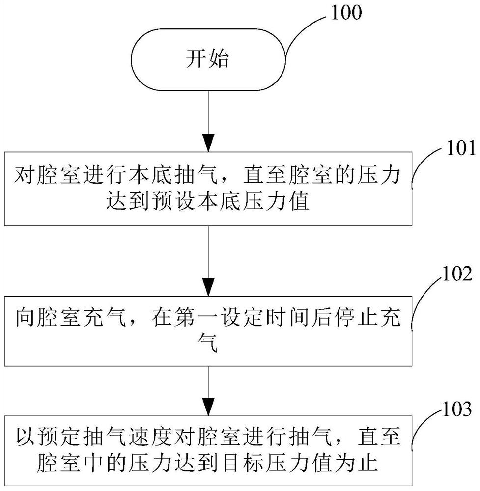
[0034] Such as figure 1 Shown is a flow chart of the pressure control method provided by the embodiment of the present invention. The pressure control method in the embodiment of the present invention is used to control the pressure of the chamber in the transmission platform, including the following steps:
[0035] Step 100: start.
[0036] Step 101: Perform background pumping on the chamber until the pressure in the chamber reaches the preset background pressure value; specifically, the preset background pressure value is determined by different chambers and processes, for example, the chamber is a transition chamber chamber and silicon wafer transfer in the transition chamber, the preset background pressure value is 50mTorr.
[0037] Step 102: Inflate the chamber with air, and stop the inflation after a first set time.
[0038] Specifically, the first set time period is a configurable value, which is determined by the operator according to process requirements, for exampl...
Embodiment 2
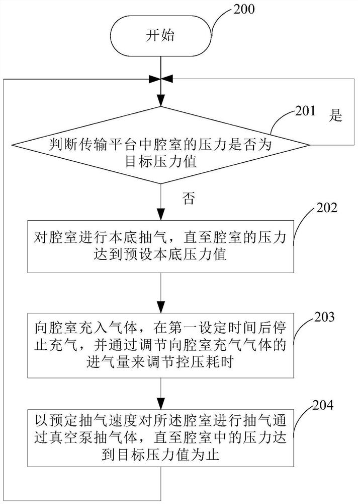
[0048] Such as figure 2 Shown is another flow chart of the pressure control method provided by the embodiment of the present invention. The pressure control method in the embodiment of the present invention includes the following steps:
[0049] Step 200: start.
[0050] Step 201: Determine whether the pressure of the chamber in the transmission platform is the target pressure value; if yes, return to step 201; otherwise, execute step 202.
[0051] Step 202: Perform background pumping on the chamber until the pressure in the chamber reaches a preset background pressure value.
[0052] Step 203: Inflate the chamber, stop the inflation after the first set time, and adjust the time-consuming pressure control by adjusting the amount of air inflated into the chamber.
[0053] Step 204: Pumping the chamber at a predetermined pumping speed until the pressure in the chamber reaches the target pressure value, and returning to step 201.
[0054] In the pressure control method provided...
Embodiment 3
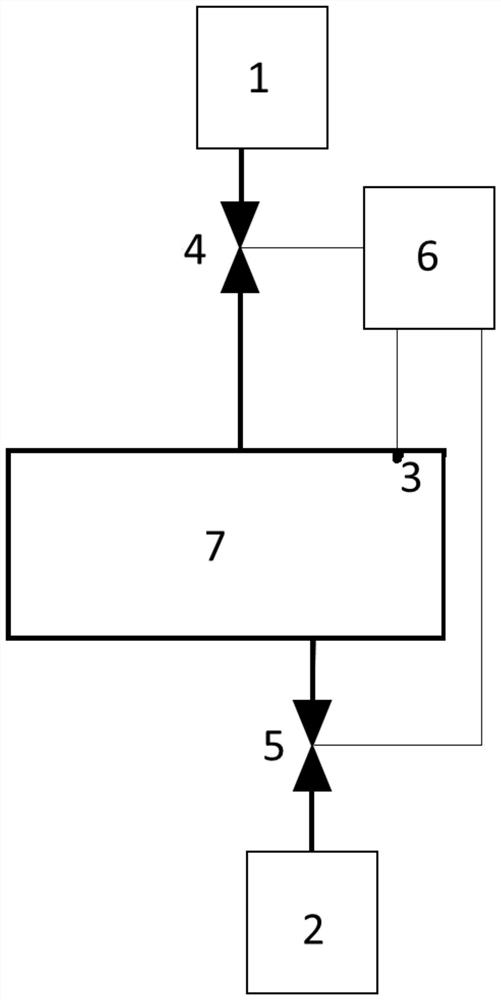
[0056] For the above pressure control method, the present invention also provides a pressure control system, which is used to control the pressure of the chamber in the transfer platform, such as figure 2 As shown, the pressure control system in this embodiment includes: a gas source 1 , a vacuum pump 2 , a pressure sensor 3 , a first switch 4 , a second switch 5 and a processor 6 .
[0057] The pressure sensor 3 is used to detect the pressure of the chamber 7 in the transmission platform, and transmit the pressure to the processor.
[0058] The first switch 4 is arranged on the gas path between the gas source 1 and the chamber 7 .
[0059] The second switch 5 is arranged on the gas path between the vacuum pump 2 and the chamber 7 .
[0060] The processor 6 performs background pumping on the chamber through the second switch 5 and the vacuum pump 2 until the pressure reaches the preset background pressure value; inflates the chamber through the first switch 4 and the gas sou...
PUM
 Abstract
Description
Claims
Application Information
 - R&D
- Intellectual Property
- Life Sciences
- Materials
- Tech Scout
- Unparalleled Data Quality
- Higher Quality Content
- 60% Fewer Hallucinations
Browse by: Latest US Patents, China's latest patents, Technical Efficacy Thesaurus, Application Domain, Technology Topic, Popular Technical Reports.
© 2025 PatSnap. All rights reserved.Legal|Privacy policy|Modern Slavery Act Transparency Statement|Sitemap|About US| Contact US: help@patsnap.com