An electric vehicle DC conversion control system and its control method
A DC conversion and control system technology, applied in electric vehicles, control/regulation systems, electric vehicle charging technology, etc., can solve the problems that DC converters cannot adapt to remote control requirements, achieve high reliability, improve safety, reduce Effects of Electromagnetic Interference
- Summary
- Abstract
- Description
- Claims
- Application Information
AI Technical Summary
Problems solved by technology
Method used
Image
Examples
Embodiment 1
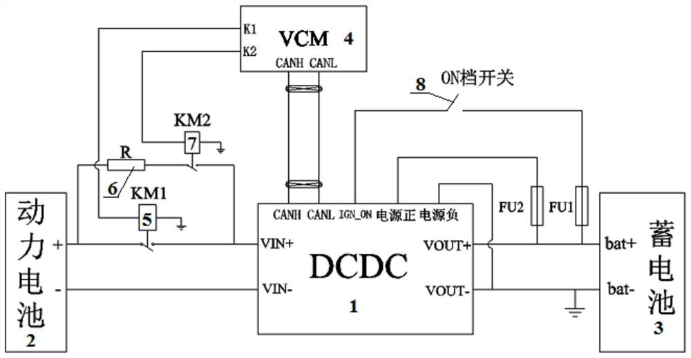
[0104] A DC conversion control system for an electric vehicle. The DC conversion control system includes: a DCDC converter 1, a power battery 2, a storage battery 3 and a VCM4. The positive pole of the power battery 2 is connected to the positive pole input terminal of the DCDC converter 1 through a charging relay 5 The positive pole of the power battery 2 is connected to the positive input terminal of the DCDC converter 1 through the resistor 6 and the pre-charging relay 7 in turn, the negative pole of the power battery 2 is connected to the negative input terminal of the DCDC converter 1, and the charging relay 5 and the control terminals of the pre-charging relay 7 are connected to the control signal output terminal of VCM4; the positive pole of the battery 3 is connected to the positive pole output terminal of the DCDC converter 1, and the positive pole of the battery 3 is connected to the DCDC converter 1 through a fuse. The positive pole of the low-voltage power supply is...
Embodiment 2
[0135] Embodiment 2 is basically the same as Embodiment 1, and its difference is:
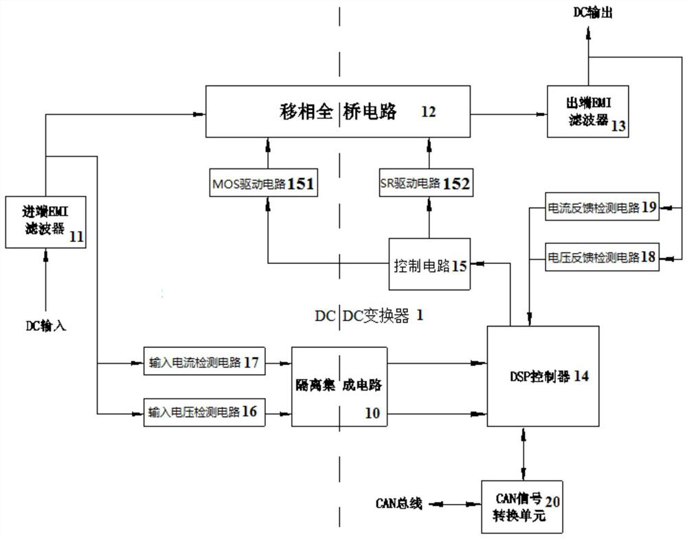
[0136] The DCDC converter 1 includes: an incoming EMI filter 11, a full-bridge circuit 12, an outgoing EMI filter 13 and a DSP controller 14, and the input of the DCDC converter 1 passes through the incoming EMI filter 11 It is electrically connected to the input end of the full bridge circuit 12, the output end of the DCDC converter 1 is electrically connected to the output end of the full bridge circuit 12 through the output EMI filter 13, and the control of the DSP controller 14 The signal output end is connected with the signal input end of the control circuit 15, and the MOS signal output end of the control circuit 15 is connected with the signal input end of the MOS drive circuit 151, and the MOS drive circuit 151 controls to move to the full bridge circuit 12 On-off of the MOS tube, the SR signal output end of the control circuit 15 is connected to the signal input end of the SR drive ci...
Embodiment 3
[0138] Embodiment 3 is basically the same as Embodiment 2, and its difference is:
[0139] The input voltage detection port is arranged on the connection line between the incoming EMI filter 11 and the full bridge circuit 12, and the input voltage detection port is connected with the signal input end of the input voltage detection circuit 16. The signal output end of the circuit 16 is connected with the input voltage detection signal end of the DSP controller 14 through the isolation integrated circuit 10; the input current detection port is arranged on the connecting line between the incoming EMI filter 11 and the full bridge circuit 12 , the input current detection port is connected to the signal input end of the input current detection circuit 17, and the signal output end of the input current detection circuit 17 is connected to the input current detection signal end of the DSP controller 14 through the isolation integrated circuit 10; The output line of described outlet EMI...
PUM
 Abstract
Description
Claims
Application Information
 - R&D
- Intellectual Property
- Life Sciences
- Materials
- Tech Scout
- Unparalleled Data Quality
- Higher Quality Content
- 60% Fewer Hallucinations
Browse by: Latest US Patents, China's latest patents, Technical Efficacy Thesaurus, Application Domain, Technology Topic, Popular Technical Reports.
© 2025 PatSnap. All rights reserved.Legal|Privacy policy|Modern Slavery Act Transparency Statement|Sitemap|About US| Contact US: help@patsnap.com


