
Cab framework, cab and rail vehicle

A driver's cab and skeleton technology, applied in the field of rail vehicles, can solve the problems of water seepage and water leakage, hidden dangers of materials, too fast glue application, etc., and achieve the effect of eliminating hidden dangers of driving safety, easy implementation, and simple structure

Active Publication Date: 2020-12-04
CRRC QINGDAO SIFANG CO LTD
View PDF10 Cites 1 Cited by
  • Summary
  • Abstract
  • Description
  • Claims
  • Application Information

AI Technical Summary

Problems solved by technology

The molding process of the driver's cab hood is usually vacuum adsorption molding, multi-combination module molding, hand lay-up molding, etc. No matter which method is used, there is a risk of internal cracks and delamination, which brings hidden dangers in terms of materials for water seepage and leakage
The gap between the hood of the driver's cab and the steel structure skeleton is sealed by manual glue sealing. There are phenomena of non-standard operation by construction personnel, such as too fast glue application, insufficient glue filling and other defects, resulting in incomplete filling of the glue joint, which is a water seepage zone to create hidden dangers
[0003] Moreover, during the operation of the vehicle, the car body is subjected to tensile and compressive forces, as well as sun exposure, acid and alkali corrosion, etc., causing deformation and cracking of the glue joints, and leakage occurs under the conditions of heavy rainfall and the impact of large water flow in the car washing machine, etc. The risk of water, water enters the interior of the driver's cab through the glue seam, and without shelter and diversion, it will cause short circuit, corrosion, and soaking of the electrical equipment and internal equipment in the driver's cab, and there is a risk of water dripping in the cab when there is a large amount of water

Method used


Image

  • Cab framework, cab and rail vehicle
  • Cab framework, cab and rail vehicle
  • Cab framework, cab and rail vehicle

Examples


Embodiment Construction

[0042] Embodiments of the present invention will be further described in detail below in conjunction with the accompanying drawings and examples. The following examples are used to illustrate the present invention, but should not be used to limit the scope of the present invention.

[0043] In the description of the embodiments of the present invention, it should be noted that the terms "center", "longitudinal", "transverse", "upper", "lower", "front", "rear", "left", "right" , "vertical", "horizontal", "top", "bottom", "inner", "outer" and other indicated orientations or positional relationships are based on the orientations or positional relationships shown in the drawings, and are only for the convenience of describing this The embodiments and simplified descriptions of the invention do not indicate or imply that the devices or elements referred to must have a specific orientation, be constructed and operate in a specific orientation, and therefore should not be construed a...


PUM


Abstract

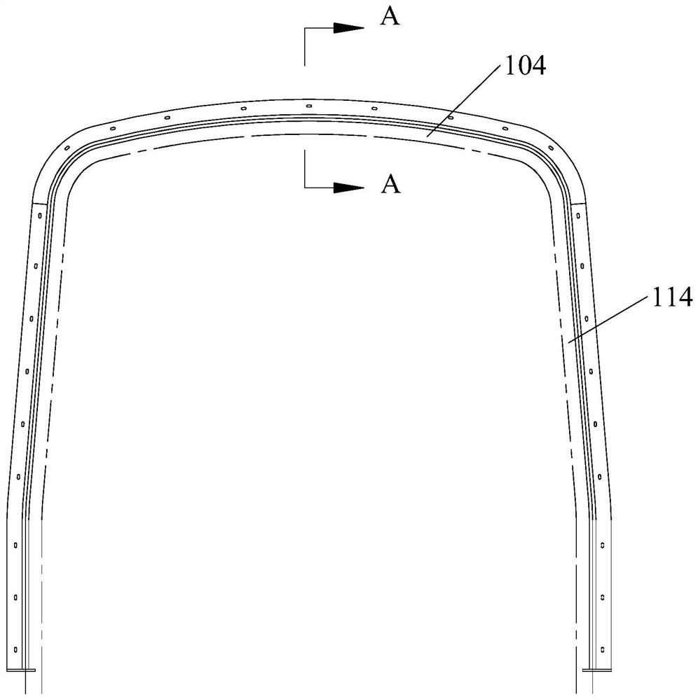
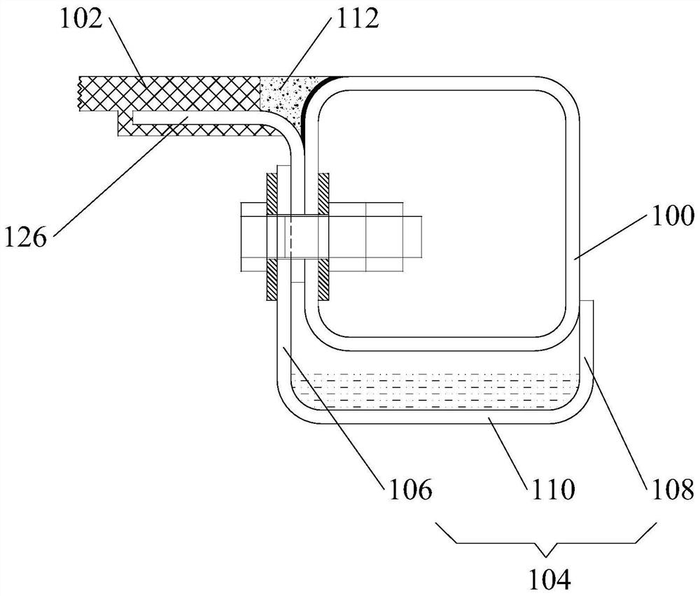
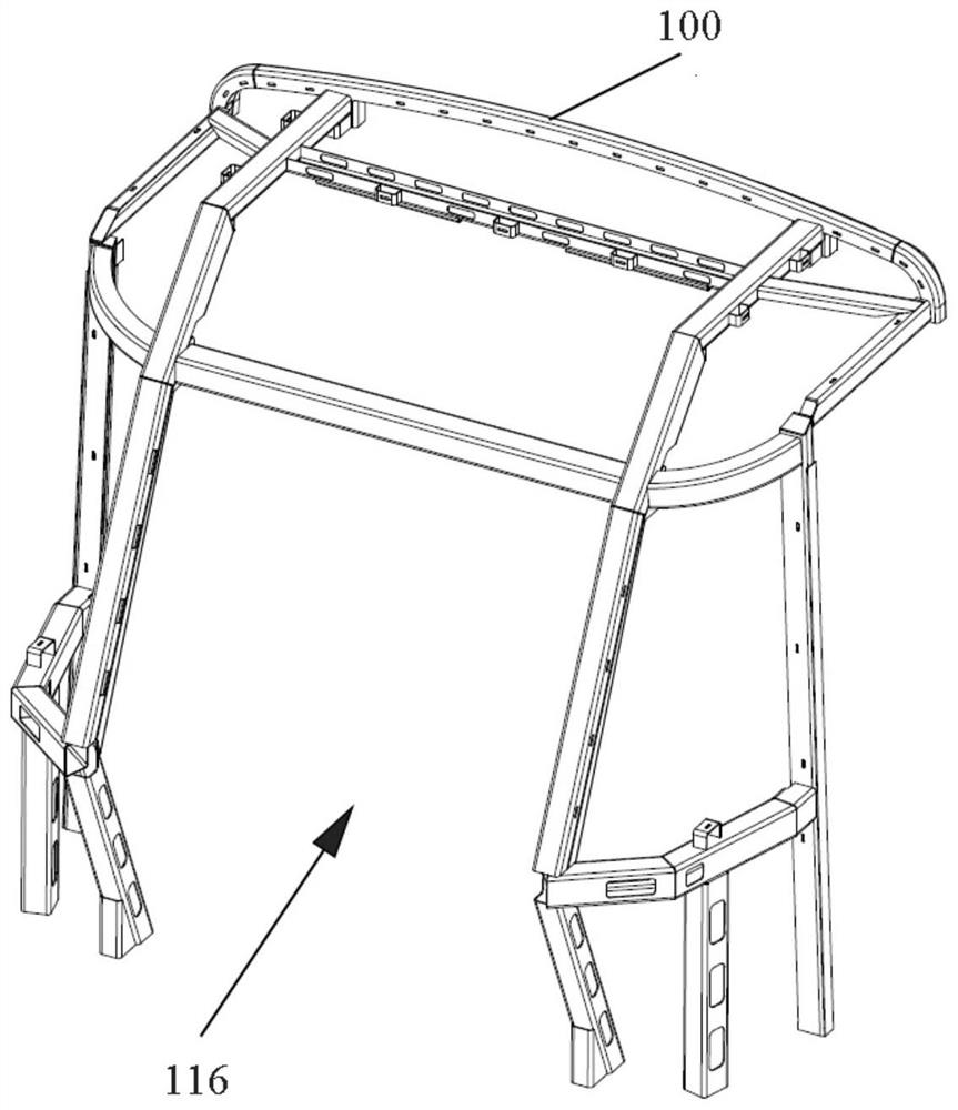
The invention relates to the technical field of railway vehicles, and provides a cab framework, a cab and a vehicle. The cab framework comprises a cab rear end beam and is suitable for being connectedto a cab hood through the cab rear end beam. A water guide groove is suitable for being connected between the cab rear end beam and the cab hood, the water guide groove is provided with a water guideopening, and the water guide opening faces a splicing seam between the cab rear end beam and the cab hood. According to the cab framework provided by the embodiment of the invention, the water guidegroove is formed between the cab rear end beam and the cab hood, so that seepage water between the cab rear end beam and the cab hood can be collected and discharged, the seepage water can be effectively prevented from entering the cab, and the influence of external seepage water on equipment in the cab is avoided; and the potential safety hazard of driving caused by water seepage is eliminated. Moreover, the cab framework is simple in structure, easy to implement and low in cost.

Description

technical field [0001] The invention relates to the technical field of rail vehicles, in particular to a driver's cab framework, a driver's cab and a rail vehicle. Background technique [0002] At present, the driver's cab of the urban rail vehicle body basically adopts the structure of the steel structure skeleton and the driver's cab hood. The external sealing method is to use the glue joint between the steel structure skeleton and the driver's cab hood for sealing, and at the same time achieve watertightness. The molding process of the driver's cab hood is usually vacuum adsorption molding, multi-combination module molding, hand lay-up molding, etc. No matter which method is used, there is a risk of internal cracks and delamination, which brings hidden dangers in terms of materials for water seepage and leakage . The gap between the hood of the driver's cab and the steel structure is sealed by manual glue sealing. There are irregularities in the operation of the construc...

Claims


Application Information

Patent Timeline
Patent Type & Authority Applications(China)
IPC IPC(8): B61D17/04
CPCB61D17/04B61D17/046Y02T30/00
Inventor 尚克明史永达林鹏韩正超王京军
Owner CRRC QINGDAO SIFANG CO LTD
Learn More