
Electric power steering device

A technology of electric power steering and steering nut, which is applied in the direction of electric steering mechanism, power steering mechanism, steering mechanism, etc., which can solve the problems of difficult overall design, high integration, and large output torque of steering device, and achieve compact structure, The effect of reducing the installation area and avoiding deformation

Active Publication Date: 2020-12-04
HANGZHOU SHIBAO AUTO STEERING GEAR
View PDF9 Cites 4 Cited by
  • Summary
  • Abstract
  • Description
  • Claims
  • Application Information

AI Technical Summary

Problems solved by technology

Compared with the traditional hydraulic power steering system (HPS), the electric power steering system (EPS) can save fuel consumption by about 3% to 5%. It has the advantages of compact structure, energy saving, environmental protection, safety and comfort, and is the development direction of the automobile power steering system. However, the output torque of the steering device is large, the integration level is high, and the overall design is difficult
Due to practical factors such as the large load on the steering axle of heavy vehicles (generally more than 4 tons) and the singleness of the layout of the power steering device (usually located in the power cabin), the use of rack and pinion steering devices or steering column steering devices cannot meet the requirements. , it is necessary to adopt a recirculating ball structure with high overall structural strength and strong impact resistance, and the current recirculating ball steering structure only exists in heavy-duty hydraulic power steering devices and has nothing to do with electric power steering systems

Method used


Image

  • Electric power steering device
  • Electric power steering device
  • Electric power steering device

Examples


Embodiment 1

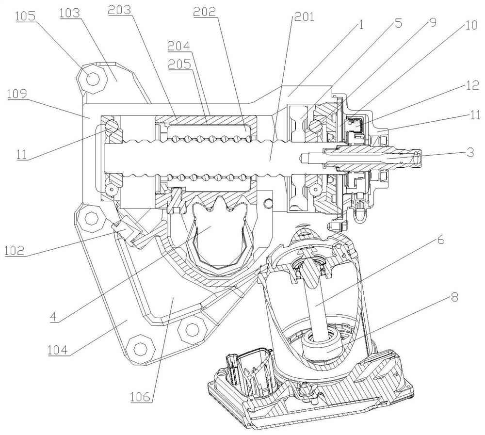
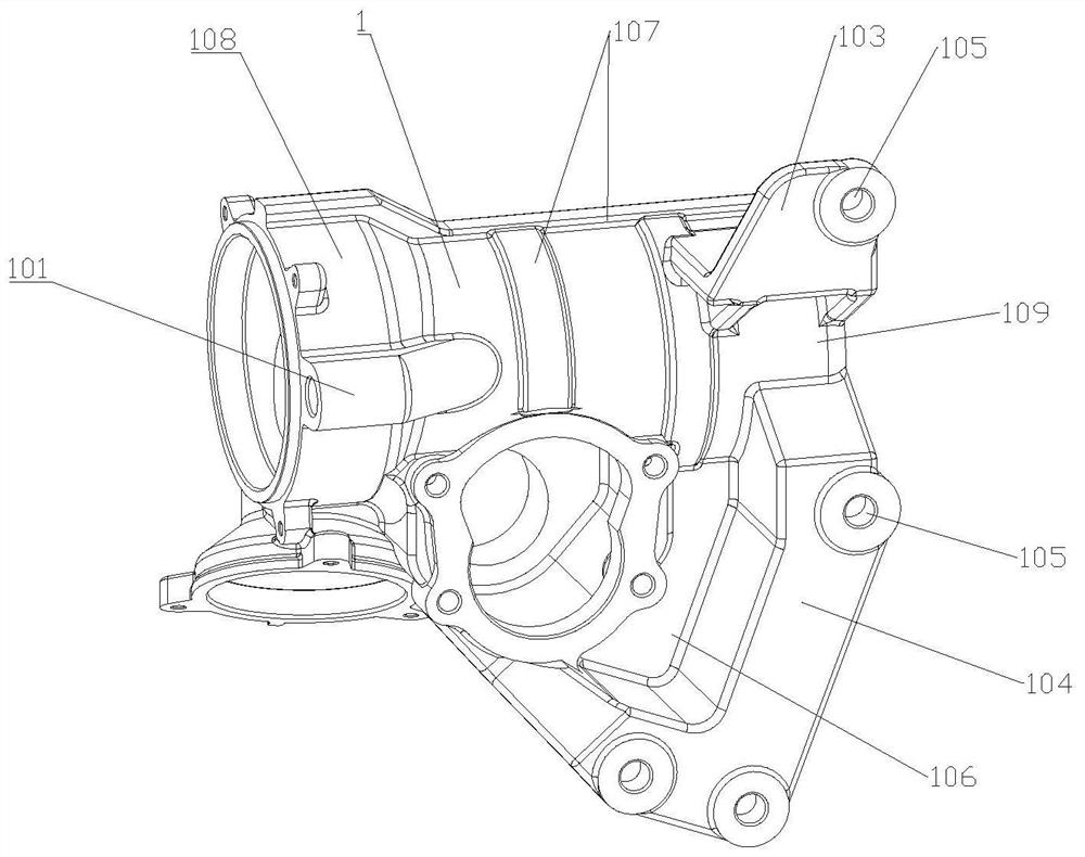
[0030] combined with Figure 1-5, the electric power steering device of this embodiment includes a housing 1, a nut and screw assembly 2, an input shaft 3, an output shaft 4, a worm wheel 5, a worm 6, a torque sensor 12 and a motor 8, wherein: the housing 1 is installed with a nut and screw assembly 2, one end of the nut and screw assembly 2 is installed inside the housing, and the other end of the nut and screw assembly 2 protrudes to the outside of the housing and is connected to the input shaft 3; the input shaft 3 is used to connect the steering wheel; the output shaft 4 is installed in the housing 1 along the direction perpendicular to the nut and screw assembly 2; the worm wheel 5 is sleeved on the nut and screw assembly 2 One end connected to the input shaft 3, and the worm gear 5 is located in the housing; the worm 6 is installed obliquely inside the housing 1, one end of the worm 6 meshes with the worm gear 5, and the other end is connected with the motor 8; the torqu...

Embodiment 2

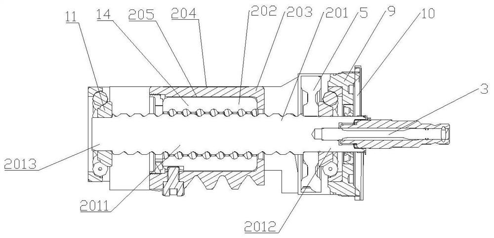
[0032] combined with Figure 1-5 , the electric power steering device of this embodiment, compared with the technical solution of Embodiment 1, can be improved as follows: the nut and screw assembly 2 includes a screw 201, a steering nut 203 and a screw nut 202, the screw The rod nut 202 is looped on the screw rod 201, the steering nut 203 is sleeved on the outer periphery of the screw nut 202, the steering nut 203 is engaged with the output shaft 4, and there is a first shaft between the housing 1 and the steering nut 203 A gap 204, there is a second gap 205 between the steering nut 203 and the screw nut 202, the width of the first gap 204 and the width of the second gap 205 are perpendicular to the axial direction of the steering nut 203, the The width of the first slit 204 is smaller than the width of the second slit 205 . The output shaft 4 exerts a reverse radial force on the steering nut 203, and the radial force pushes the steering nut 203 to move in the radial directi...

Embodiment 3

[0034] combined with Figure 1-5 , the electric power steering device of this embodiment, compared with the technical solution of Embodiment 1 or 2, can be improved as follows: the screw rod 201 includes a screw segment 2011 and a first smooth segment 2012 arranged at one end of the screw segment 2011, so The first smooth section 2012 is sleeved with a first bearing 9 and a worm wheel 5, one end of the worm wheel 5 cooperates with the first bearing 9, and the other end of the worm wheel 5 abuts against the screw section 2011 and the first smooth section 2012 at the connected shoulders. One end of the worm gear 5 cooperates with the first bearing 9, and the other end abuts against the shaft shoulder connected between the screw segment 2011 and the first smooth segment 2012, so that the worm gear 5 is fixed between the first bearing 9 and the screw segment 2011, when When the worm gear 5 meshes with the worm screw 6, the worm gear 5 is not easy to slip and has greater transmiss...


PUM


Abstract

The invention discloses an electric power steering device, and relates to the technical field of power transmission. The device comprises a shell, a nut and screw rod assembly, an input shaft, an output shaft, a worm gear, a worm, a torque sensor and a motor, one end of the nut and screw rod assembly is installed in the shell, and the other end of the nut and screw rod assembly extends out of theshell and is connected with an input shaft; the input shaft is used for connecting a steering wheel; the worm is obliquely installed in the shell, one end of the worm is meshed with the worm gear, andthe other end of the worm is connected with the motor; and the torque sensor is arranged at the joint of the input shaft and the nut and screw rod assembly. The steering wheel is connected with the input shaft, the torque sensor transmits a force applied to the steering wheel to the motor, the motor applies the force to the worm, the worm drives the worm gear to rotate, then the worm gear transmits a steering force to the nut and screw rod assembly, and the nut and screw rod assembly drives the output shaft assembly to move repeatedly so that a power assisting function is achieved.

Description

technical field [0001] The invention relates to the technical field of power transmission technology, in particular to an electric power steering device. Background technique [0002] Hyundai automobile technology pursues the three goals of high efficiency and energy saving, high comfort and high safety. As one of the most important subsystems of a car, the development of the steering system has been striving to achieve these goals. Compared with the traditional hydraulic power steering system (HPS), the electric power steering system (EPS) can save fuel consumption by about 3% to 5%. It has the advantages of compact structure, energy saving, environmental protection, safety and comfort, and is the development direction of the automobile power steering system. However, the output torque of the steering device is large, the requirements for integration are high, and the overall design is difficult. Due to practical factors such as the large load on the steering axle of heav...

Claims


Application Information

Patent Timeline
Patent Type & Authority Applications(China)
IPC IPC(8): B62D5/04
CPCB62D5/0454B62D5/0445
Inventor 朱胜峰朱兴旺虞忠潮蔡磊杰施国标胡燕军
Owner HANGZHOU SHIBAO AUTO STEERING GEAR
Learn More