Automatic capping device for beverage production

An automatic and beverage technology, which is applied in the directions of tightly closing containers with lids, packaging, and application, can solve problems such as affecting product quality, difficult to ensure cleanliness and hygiene, and difficult for workers to withstand mass production tasks on production lines, achieving high automation strength. Effect

Inactive Publication Date: 2020-12-04
吕瑞雪
View PDF0 Cites 2 Cited by
  • Summary
  • Abstract
  • Description
  • Claims
  • Application Information

AI Technical Summary

Problems solved by technology

[0003] The existing capping process is mostly performed by workers manually. This manual operation is labor-intensive, and it is difficult for workers to withstand the rapid mass production tasks on the production line. Moreover, it is difficult to ensure cleanliness and sanitation by manual capping operations, which affects product quality.

Method used


Image

  • Automatic capping device for beverage production
  • Automatic capping device for beverage production
  • Automatic capping device for beverage production

Examples


Embodiment 1

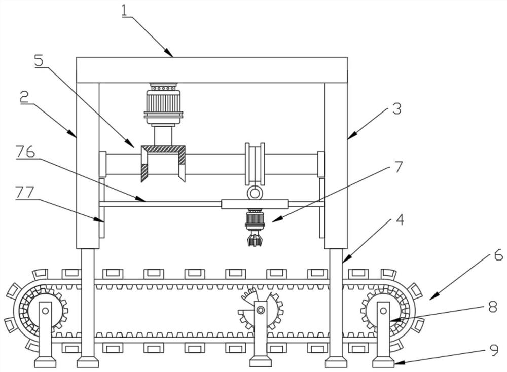
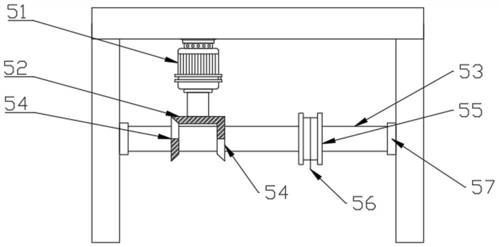
[0024] see Figure 1-5 , an automatic upper cover device for beverage production, comprising a beam plate 1, a left side plate 2, a right side plate 3, a support column 4, a drive mechanism 5, a transport mechanism 6 and an upper cover mechanism 7, the left side plate 2 and the The front and rear ends of the bottom of the right side plate 3 are fixedly connected with the support columns 4, and the top surfaces of the left side plate 2 and the right side plate 3 are fixedly connected to the left and right sides of the bottom surface of the beam plate 1;

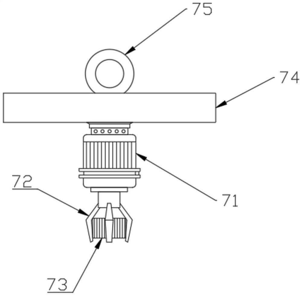
[0025] The upper cover mechanism 7 includes a second motor 71, a three-claw gripper 72, a bottle cap 73 and a fixed frame 74, the bottom surface of the fixed frame 74 is fixedly connected with the second motor 71, and the output shaft of the second electric motor The bottom end is provided with the three-claw grip 72, and the three-claw grip 72 is clamped with the bottle cap 73;

[0026] The transport mechanism 6 includes a c...

Embodiment 2

[0034] This embodiment is a further improvement made on the basis of Embodiment 1, specifically as follows:

[0035] see Figure 1-5 , the left and right sides of the fixed frame 74 are fixedly connected with a balance bar 76, and the end of the balanced bar 76 away from the fixed frame 74 is slidably installed on a slide rail 77, and the bottom surface of the slide rail 77 is fixedly connected with the left side On the side wall adjacent to the board 2 and the right side board 3 , the balance bar 76 acts as a balance guide to avoid shaking during the up and down reciprocating movement of the fixing frame 74 .

[0036] The bottom ends of the column 8 and the support column 4 are all fixedly connected with a shock-proof foot pad 9, and the shock-proof foot pad 9 has played a role of shock absorption and shock absorption, reducing the vibration generated by the device when the motor rotates far away, increasing the The overall stability of the device.

[0037] The last few point...


PUM


Abstract

The invention discloses an automatic capping device for beverage production. The automatic capping device comprises a cross beam plate, a left side plate, a right side plate, supporting columns, a driving mechanism, a conveying mechanism and a capping mechanism, and is characterized in that the front and rear ends of the bottom surfaces of the left side plate and the right side plate are fixedly connected with the supporting columns correspondingly; and the top surfaces of the left side plate and the right side plate are fixedly connected to the left side and the right side of the bottom surface of the cross beam plate. According to the automatic capping device disclosed by the invention, beverage bottles are conveyed through transmission of a transmission belt; due to movable connection of a first fan-shaped roller and a second fan-shaped roller, when the first fan-shaped roller is meshed with the transmission belt, the transmission belt generates transmission movement; when the second fan-shaped roller is meshed with the transmission belt, the second fan-shaped roller can move along a blank fan-shaped area of the first fan-shaped roller, and at the moment, the transmission belt stops moving; when the transmission belt stops, capping action on the beverage bottles is completed; when the first fan-shaped roller is meshed with the transmission belt again, the transmission belt achieves transmission movement again, so that intermittent movement of the transmission belt is achieved.

Description

technical field [0001] The invention relates to the technical field of food processing and production, in particular to an automatic capping device for beverage production. Background technique [0002] Beverages are liquids for human or livestock drinking, which are packaged in quantitative quantities for direct drinking or brewed or brewed with water in a certain proportion, and products with an ethanol content (mass weight) of no more than 0.5%. In the beverage production process, after the beverage bottle is filled, the bottle cap needs to be screwed on the mouth of the beverage bottle. [0003] The existing capping process is mostly performed by workers manually. This manual operation is labor-intensive, and it is difficult for workers to withstand the rapid mass production tasks on the production line. Moreover, it is difficult to ensure cleanliness and sanitation by manual capping operations, which affects product quality. . Contents of the invention [0004] The ...

Claims


Application Information

Patent Timeline
Patent Type & Authority Applications(China)
IPC IPC(8): B67B3/20
CPCB67B3/204B67B3/2053
Inventor 吕瑞雪
Owner 吕瑞雪
Why Eureka
Try Eureka