A portable electrospinning device

An electrospinning and equipment technology, applied in the field of portable electrospinning equipment, can solve problems such as inconvenient operation, and achieve the effects of easy portability, high push rod strength, and stable force

Active Publication Date: 2022-04-29
LANZHOU BAIYUAN GENE TECH
View PDF24 Cites 0 Cited by
  • Summary
  • Abstract
  • Description
  • Claims
  • Application Information

AI Technical Summary

Problems solved by technology

[0005] Therefore, the technical problem to be solved by the present invention is that the portable electrospinning device in the prior art is inconvenient to operate when injecting the spinning solution into the injection cylinder.

Method used


Image

  • A portable electrospinning device
  • A portable electrospinning device
  • A portable electrospinning device

Examples


Embodiment 1

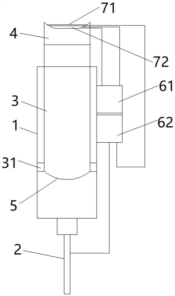
[0041] This embodiment provides an electrospinning device, such as figure 1 As shown, it includes an injection cylinder 1 , a push rod 3 , a blocking component 4 and a one-way throttling component 5 .

[0042]Wherein, the end of the injection cylinder 1 close to the needle 2 is the first front end, and the stainless steel needle 2 is installed on the opening of the first front end of the injection cylinder 1 . The push rod 3 is a hollow structure, which has a hollow cavity. The hollow cavity is arranged axially through the push rod 3. The end of the push rod 3 close to the needle 2 is the second front end, and the end facing away from the needle 2 is the second rear end. The hollow cavity is in the Two ends of the push rod 3 respectively form a second front opening and a second rear opening.

[0043] The injection cylinder 1 and the push rod 3 are both hollow cylinders. The outer diameter of the push rod 3 is larger than the radius of the injection body. When the operator pre...

Embodiment 2

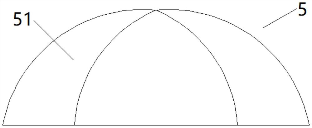
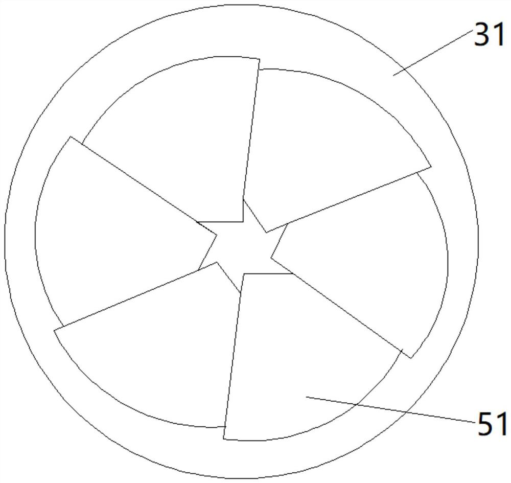
[0054] This embodiment provides an electrospinning device, see figure 2 and image 3 , it differs from Embodiment 1 in that the one-way throttling member 5 includes a plurality of baffles 51, the baffles 51 are in the shape of fan-shaped petals, any baffle 51 has a fixed end and a free end, and the baffles are rigid materials Made, the fixed end of the catch is hinged on the end surface of the annular boss 31, the free end of the catch is inclined inward toward the center line of the push rod 3, and the adjacent ends of any two adjacent catches 51 are pressed against each other. Together, the plurality of blocking pieces 51 are pressed together to form a closed bud shape, and a second cavity protruding toward the needle 2 is formed at the second front end of the push rod 3 .

[0055] When in use, the spinning solution is located in the first cavity, pushes the push rod 3, the free ends of the plurality of baffles 51 gather at the centerline of the push rod 3, the second cavi...


PUM


Abstract

The invention provides a portable electrospinning device, which includes an injection cylinder, a push rod, a blocking component and a one-way throttling component. Wherein, the push rod is a hollow structure, and the second front end of the push rod is sealed with a one-way throttling component. When the spinning solution in the first cavity is used up, pull the push rod outward to increase the volume of the first cavity, remove the plugging part from the push rod, and open the second rear end of the push rod into the hollow cavity of the push rod When the spinning solution is injected, the pressure of the medium in the hollow cavity increases, the one-way throttling part opens, and the spinning solution enters the first cavity from the hollow cavity of the push rod, so that the injection or replacement of the spinning solution is easy to operate; in addition, it is convenient Add medicine powder such as anti-inflammatory drugs to the push rod, and bring the medicine powder into the first inner cavity when the spinning solution is injected, and the spinning with medicine powder is deposited on the wound to facilitate wound healing; the electrospinning equipment is small in size and easy to carry; use It is convenient to move the spinning equipment along with the shape of the patient's wound, and spin according to the shape of the wound to achieve wound healing.

Description

technical field [0001] The invention relates to the technical field of electrostatic spinning, in particular to a portable electrostatic spinning device. Background technique [0002] Electrospinning is one of the simplest and most efficient methods for preparing one-dimensional micro-nano fibers. Compared with traditional nanomaterials preparation technology, it has the advantages of simple processing equipment, wide source of raw materials, low spinning cost, and large-scale preparation. In recent years, To receive extensive research reports at home and abroad. Micro-nano fibers processed by electrospinning technology have excellent characteristics such as high specific surface area, large aspect ratio (ie length / diameter) and unique physical and chemical properties. Sustained release, flexible devices and other fields show great application potential. The principle of the electrospinning method is: under the action of a high-voltage electric field, the polymer solution ...

Claims


Application Information

Patent Timeline
Patent Type & Authority Patents(China)
IPC IPC(8): D01D5/00
CPCD01D5/0061D01D5/0069D01D5/0092
Inventor 李春李琳
Owner LANZHOU BAIYUAN GENE TECH
Why Eureka
Try Eureka