Direction-changeable centrifugal wind wheel and centrifugal fan thereof

A centrifugal wind wheel and direction changing technology, which is applied in the direction of mechanical equipment, non-variable pumps, radial flow pumps, etc., can solve the problems that are difficult to meet the requirements of modern homes, increase the volume of fans, etc., and achieve compact structure and low wind pressure loss. small, reduced size effect

Inactive Publication Date: 2020-12-04
柴俊麟
View PDF0 Cites 1 Cited by
  • Summary
  • Abstract
  • Description
  • Claims
  • Application Information

AI Technical Summary

Problems solved by technology

This increases the volume of the fan to a certain extent, which is difficult to meet the requirements of modern homes

Method used


Image

  • Direction-changeable centrifugal wind wheel and centrifugal fan thereof
  • Direction-changeable centrifugal wind wheel and centrifugal fan thereof
  • Direction-changeable centrifugal wind wheel and centrifugal fan thereof

Examples


Embodiment 1

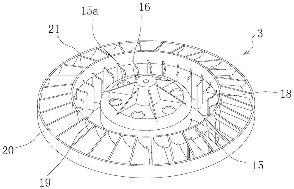
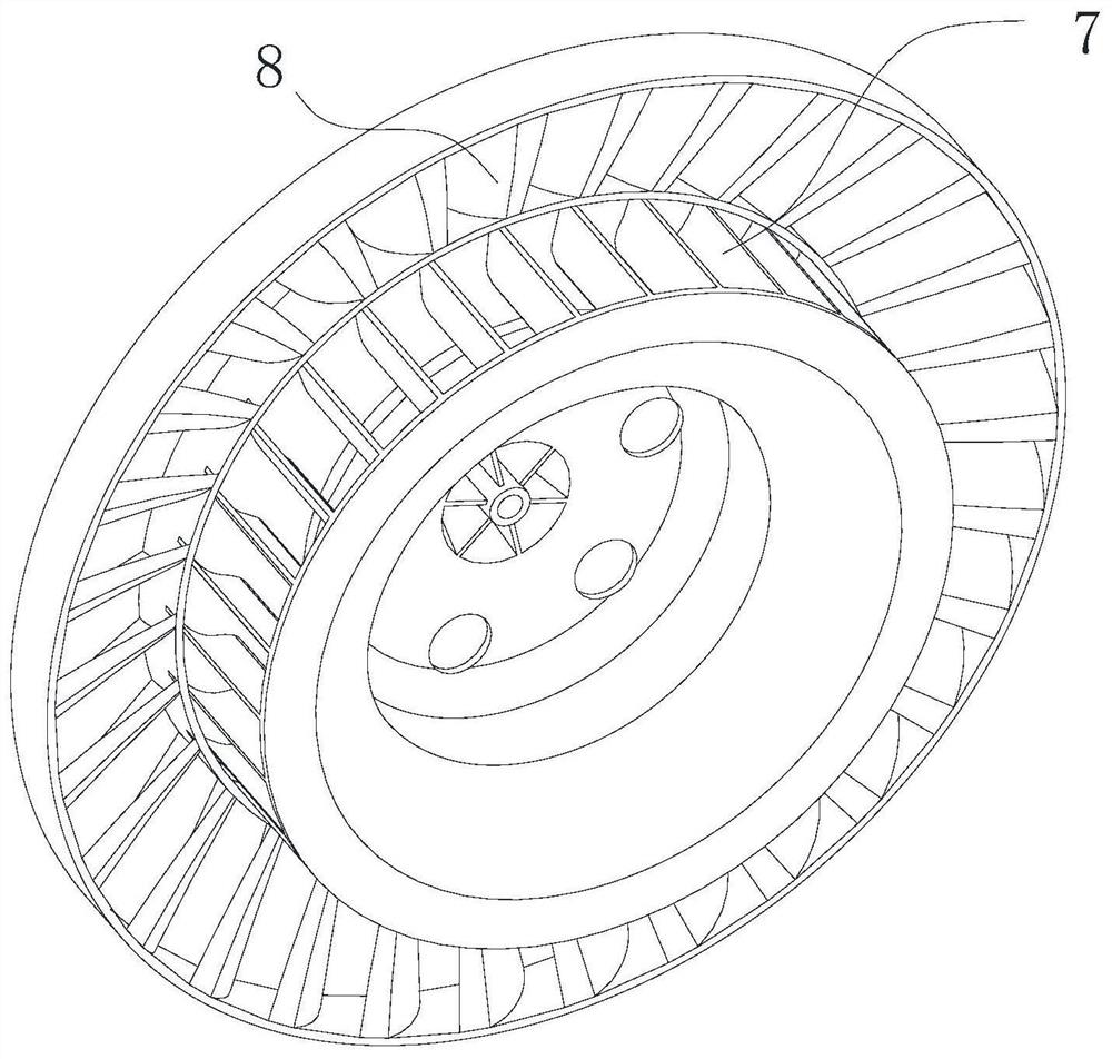
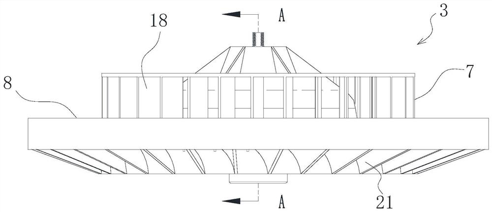
[0033] Such as figure 1 , figure 2 As shown, the direction-changing centrifugal wind wheel 3 of the present invention includes several blades, and the blades include air inlet blades 18 and air outlet blades 21, and several air inlet blades 18 form the air inlet impeller assembly 7, and several air outlet blades 21 The air outlet impeller assembly 8 is formed, the air inlet blade 18 is arranged axially, the air outlet blade 21 is arranged along the circumference of the air outlet impeller assembly 8, and the air outlet side of the air inlet blade 18 corresponds to the outlet blade 21 Intake side.

[0034] In this embodiment, the air outlet impeller assembly 8 is located at the upper end of the air inlet impeller assembly 7, and the air inlet impeller assembly 7 is in a cylindrical shape. Located on the outer wall of the inlet impeller assembly 7 , the outlet impeller assembly 8 is in the shape of a disc inclined downward. In principle, the acute angle α between the air inl...

Embodiment 2

[0039] Such as image 3 , Figure 4 As shown, the difference between this embodiment and Embodiment 1 is: in this embodiment, the air outlet impeller assembly 8 is located at the lower end of the air inlet impeller assembly 7, and at the same time, the air outlet impeller assembly 8 is in the shape of an upwardly inclined disc .

[0040] The wind rotor of this embodiment can realize wind inlet and outlet from different sides on the basis of not needing additional air ducts.

Embodiment 3

[0042] Such as Figure 5 , Figure 6 and Figure 7 As shown, the centrifugal fan of this embodiment uses the centrifugal fan wheel of Embodiment 1. It specifically includes: a fan housing 1, the motor 2 is arranged in the fan housing 1, the output shaft of the motor 2 is connected with the wind wheel 3, the top of the fan housing 1 is open, and the top of the fan housing 1 There is an air inlet isolation cover 4, and the top of the fan casing 1 is provided with a cover plate 1a, which is used to connect with the air inlet isolation cover 4, or to facilitate connection with the ceiling or decorative panels when installing a bathroom heater. The air inlet isolation cover 4 has An air inlet 5, an air outlet 6 is formed between the outer wall of the air inlet isolation cover 4 and the top of the fan casing 1, and the wind wheel 3 includes an air inlet impeller assembly 7 and an air outlet impeller assembly 8, and the air inlet of the air inlet impeller assembly 7 The side corre...


PUM


Abstract

The invention belongs to the technical field of fluid machines, and particularly relates to a direction-changeable centrifugal wind wheel and a centrifugal fan thereof. The wind wheel comprises multiple blades, the blades comprise air inlet blades and air outlet blades, the multiple air inlet blades form an air inlet impeller assembly, the multiple air outlet blades form an air outlet impeller assembly, the air inlet blades are axially arranged, the air outlet blades are arranged in the circumferential direction of the air outlet impeller assembly, and the air outlet sides of the air inlet blades correspond to the air inlet sides of the air outlet blades. The centrifugal fan comprises a fan shell, a motor is arranged in the fan shell, and an output shaft of the motor is connected with thewind wheel. By means of the direction-changeable centrifugal wind wheel and the centrifugal fan thereof, free conversion between the air inlet direction and the air outlet direction of the fan can beachieved, an air duct structure is not needed, and meanwhile the beneficial effects that noise is low and air pressure losses are few are achieved.

Description

technical field [0001] The invention belongs to the technical field of fluid machinery, and relates to a direction-changing centrifugal wind wheel and a centrifugal fan thereof. Background technique [0002] The fan is a device for gas compression and gas delivery, which converts the mechanical energy of rotation into gas pressure energy and kinetic energy, and sends the gas out. According to the flow direction of the airflow after entering the wind wheel, the fans can be divided into centrifugal fans, axial flow fans and diagonal flow (mixed flow) fans. Among them, the centrifugal fan means that the airflow mainly flows in the radial direction after entering the impeller of the fan in the axial direction. One of the advantages of centrifugal fans is the ability to generate wind pressure. [0003] However, in the existing centrifugal fan, in order to form sufficient wind pressure, it is necessary to adopt a supporting volute structure to form an air duct, so that the flowi...

Claims


Application Information

Patent Timeline
Patent Type & Authority Applications(China)
IPC IPC(8): F04D29/28F04D29/30F04D29/66F04D25/08F04D17/16F04D29/42F04D29/44
CPCF04D17/165F04D25/08F04D29/281F04D29/30F04D29/4253F04D29/441F04D29/663F04D29/666F04D29/667
Inventor 柴俊麟
Owner 柴俊麟
Why Eureka
Try Eureka