
Gas injection and distribution device and control method thereof

A technology of gas distribution device and control method, which is applied to furnace control devices, furnaces, lighting and heating equipment, etc., can solve problems such as gas enrichment and explosion, impact on quality of sintered finished ore, and combustion.

Active Publication Date: 2022-05-20
SGIS SONGSHAN CO LTD
View PDF4 Cites 0 Cited by
  • Summary
  • Abstract
  • Description
  • Claims
  • Application Information

AI Technical Summary

Problems solved by technology

[0005] The gas injection device under the existing technology, due to the frequent fluctuation of the negative pressure value of the material surface in the hood due to various factors of the working conditions of the sintering machine, can easily cause the mismatch between the negative pressure value of the material surface and the height of the injection pipe row, so in the long-term production There are two problems in the following:
[0006] 1. The negative pressure on the material surface is too high: the injected gas will be sucked into the material layer by the excessively high negative pressure on the material surface as soon as it exits the nozzle hole, and there is not enough time to mix and dilute with the atmosphere in the hood, resulting in the gas entering the material layer The concentration is not the design concentration and is extremely uneven, which will cause uncontrollable multi-position combustion of gas in the material layer, which will not only affect the auxiliary effect of gas injection, but also have a negative impact on the quality of sintered finished ore;
[0007] 2. Negative pressure on the material surface is too low: the ejected gas will scatter and escape due to insufficient downward suction to pull it, not only cannot form a stable and orderly flow field in the hood, but will easily cause gas overflow or gas Enrichment of explosion accidents greatly reduces production safety factor

Method used


Image

  • Gas injection and distribution device and control method thereof
  • Gas injection and distribution device and control method thereof
  • Gas injection and distribution device and control method thereof

Examples


Embodiment Construction

[0051]In order to make the purposes, technical solutions and advantages of the embodiments of the present application clearer, the technical solutions in the embodiments of the present application will be clearly and completely described below in conjunction with the drawings in the embodiments of the present application. Obviously, the described embodiments It is a part of the embodiments of this application, not all of them. The components of the embodiments of the application generally described and illustrated in the figures herein may be arranged and designed in a variety of different configurations.

[0052] Accordingly, the following detailed description of the embodiments of the application provided in the accompanying drawings is not intended to limit the scope of the claimed application, but merely represents selected embodiments of the application. Based on the embodiments in this application, all other embodiments obtained by persons of ordinary skill in the art wi...


PUM


Abstract

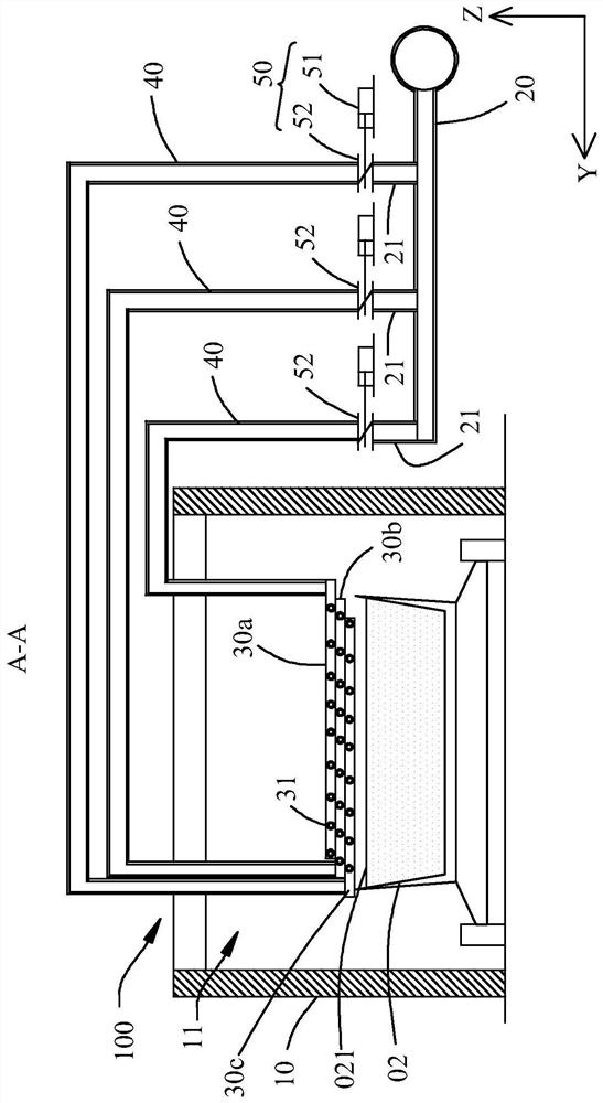
The application relates to a gas injection and distribution device and a control method thereof, belonging to the technical field of sintering equipment. The gas injection and gas distribution device includes an injection hood, an injection branch pipe, a multi-layer injection pipe row, a material surface negative pressure detector and a control system. One end of the injection branch pipe is used to connect with the gas source, and the other end of the injection branch pipe has multiple branch pipes; Distributed at intervals, each row of injection pipes is connected to a branch pipe through a flow control valve; the material level negative pressure detector is installed upstream of the injection hood to detect the sintering material of the sintering machine trolley to enter the injection hood The material surface negative pressure; the control system is electrically connected with the material surface negative pressure detector and the flow control valve, and the control system is used to control the work of the flow control valve in response to the material surface negative pressure value detected by the material surface negative pressure detector, so as to achieve at least One layer of blowing pipes blows gas. The gas injection and distribution device has good auxiliary effect and high safety factor.

Description

technical field [0001] The present application relates to the technical field of sintering equipment, in particular, to a gas injection and distribution device and a control method thereof. Background technique [0002] The sintering process is a key link in the ironmaking process. Its principle is to mix various powdery iron-containing raw materials with an appropriate amount of fuel and flux, add an appropriate amount of water, mix and pelletize the material on the sintering equipment to make the material A series of physical and chemical changes, sintered into blocks, which are sent to the blast furnace for the next step. [0003] In order to reduce the coke ratio and smelting cost of blast furnace ironmaking, blast furnaces often require high strength and high reducibility for sintered ore. Therefore, during the sintering process, it is generally necessary to inject fuel on the surface of the sintered material to improve the strength and reducibility of the sintered mat...

Claims


Application Information

Patent Timeline
Patent Type & Authority Patents(China)
IPC IPC(8): F27D99/00F27B21/08F27B21/14
CPCF27D99/0033F27D19/00F27B21/00F27D2099/004F27M2003/04F27D2019/004Y02P10/20
Inventor 陈科李圭文谢金祥谭贤会黄寿坚莫庆芳王勤福刘高鑫邓海东靳向阳
Owner SGIS SONGSHAN CO LTD
Learn More