Steam flow measuring device and steam injection pipeline using same

A technology of steam flow and measuring device, which is applied in the direction of measuring device, liquid/fluid solid measurement, measurement, etc., can solve the problem of high cost of flow measuring device, and achieve the effect of improving safety and reliability, high mechanical performance and prolonging service life.

Active Publication Date: 2020-12-04
CHINA PETROLEUM & CHEM CORP +1
View PDF10 Cites 2 Cited by
  • Summary
  • Abstract
  • Description
  • Claims
  • Application Information

AI Technical Summary

Problems solved by technology

[0004] The purpose of the present invention is to provide a steam flow measuring device to solve the problem of high cost of the flow measuring device in the prior art; the purpose of the present invention is also to provide a steam injection pipeline to improve the The effective utilization of steam, thereby improving the thermal recovery of heavy oil

Method used


Image

  • Steam flow measuring device and steam injection pipeline using same
  • Steam flow measuring device and steam injection pipeline using same
  • Steam flow measuring device and steam injection pipeline using same

Examples


specific Embodiment 1

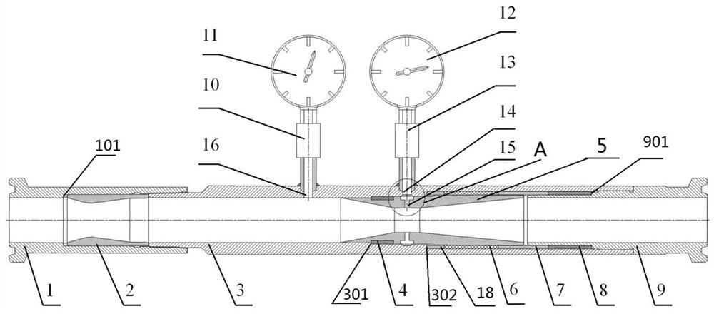
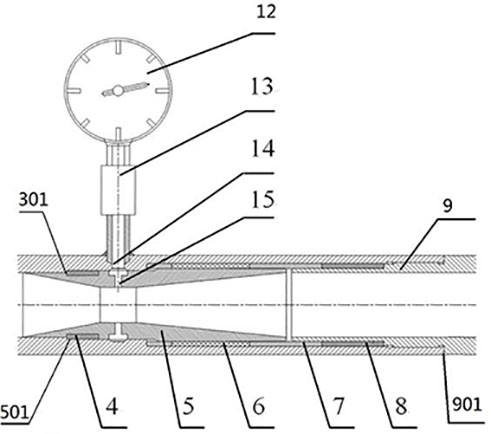
[0100] Such as figure 1 with figure 2 As shown, the steam flow measuring device includes a pipe main body 3 and two hoop heads, and the two hoop heads are screwed to both axial ends of the pipe main body 3 . The above two clamp heads are used as joints of the pipe main body for connection with the steam injection pipeline. The front side of the pipe main body 3 is provided with a flow blocking member 2 , and a Venturi tube 5 is fixed inside the pipe main body 3 , and the flow blocking member 2 is arranged on the front side of the Venturi pipe 5 . The choke piece 2 is a tubular structure, the inner diameter of the choke piece 2 shrinks from front to back and then gradually expands, and is used to mix the steam flowing through the choke piece 2 in a throttling manner. The steam flow measuring device also includes a pressure measuring device, and the pressure measuring device obtains the steam pressure difference between the inlet of the venturi tube 5 and the throat through m...

specific Embodiment 2

[0116] The steam pressure difference in the above-mentioned embodiment 1 is obtained by subtracting the pressure measured by the front pressure gauge arranged at the inlet of the Venturi tube and the pressure measured by the rear pressure gauge arranged at the throat of the Venturi tube; as Figure 4 As shown, in this embodiment, a differential pressure transmitter 17 is connected between the inlet pressure hole 16 and the throat pressure introduction hole 14, and the steam pressure at the inlet of the Venturi tube and the throat is directly obtained through the differential pressure transmitter 17 difference.

specific Embodiment 3

[0118] The baffle in the above-mentioned embodiment 1 is composed of a baffle; the baffle in this embodiment is composed of a porous plate, that is, the porous plate replaces the baffle in the above-mentioned embodiment 1, and the steam flowing into the main body of the pipe flows When passing through the porous plate, the two phases of the vapor and night of the steam are fully mixed through the throttling effect of the porous plate and the collision between the fluid and the hole wall of the porous plate.


PUM


Abstract

The invention relates to the technical field of steam flow measurement, in particular to a steam flow measuring device and a steam injection pipeline using the same. The steam flow measuring device comprises a flow choking piece and a venturi tube, wherein the venturi tube is located behind the flow choking piece, and a throat pressure tapping hole is formed in the throat of the venturi tube. Thedevice further comprises a tube main body; a front joint and a rear joint are respectively arranged at the front end and the rear end of the tube main body and are used for connecting the steam flow measuring device to a steam injection pipeline in series; the venturi tube is fixed in the tube main body; an inlet pressure tapping hole and a throat pressure leading hole are formed in the tube mainbody; the inlet pressure tapping hole is formed in the front side of the venturi tube so as to be communicated with an inlet of the venturi tube; the throat pressure leading hole is communicated withthe throat pressure tapping hole. The steam flow measuring device further comprises a front sealing structure and a rear sealing structure; the front sealing structure is arranged between the tube main body and the venturi tube; and the rear sealing structure is arranged between the tube main body and the venturi tube. According to the steam flow measuring device, the overall material and processing cost of the measuring device can be greatly reduced.

Description

technical field [0001] The invention relates to the technical field of steam flow measurement, in particular to a steam flow measurement device and a steam injection pipeline using the device. Background technique [0002] Shallow heavy oil thermal recovery wells are usually developed by steam huff and puff, which injects high-temperature steam into the well to heat the formation heavy oil, and then lifts the oil through the pumping unit. Since each boiler produces a large amount of steam but the amount of steam injected into a single well is small, one boiler is usually used to inject wet saturated steam into multiple heavy oil wells. At present, the cost of equipment is as high as 200,000 yuan to achieve accurate measurement of vapor-liquid two-phase flow by adopting the flow-splitting and phase-separation measurement technology. Due to the low oil price and high development cost, the flow-splitting and phase-separation metering technology cannot meet the needs of low-cos...

Claims


Application Information

Patent Timeline
Patent Type & Authority Applications(China)
IPC IPC(8): G01F1/44G01F15/18G01F15/00E21B43/24E21B47/00
CPCG01F1/44G01F15/185G01F15/00G01F15/005E21B43/24E21B47/00
Inventor 马宏伟范喜群赵林沈威魏振国张景辉周文玉王小勇
Owner CHINA PETROLEUM & CHEM CORP
Why Eureka
Try Eureka